

Leaderboard


Popular Content
Showing content with the highest reputation on 09/11/20 in all areas
-
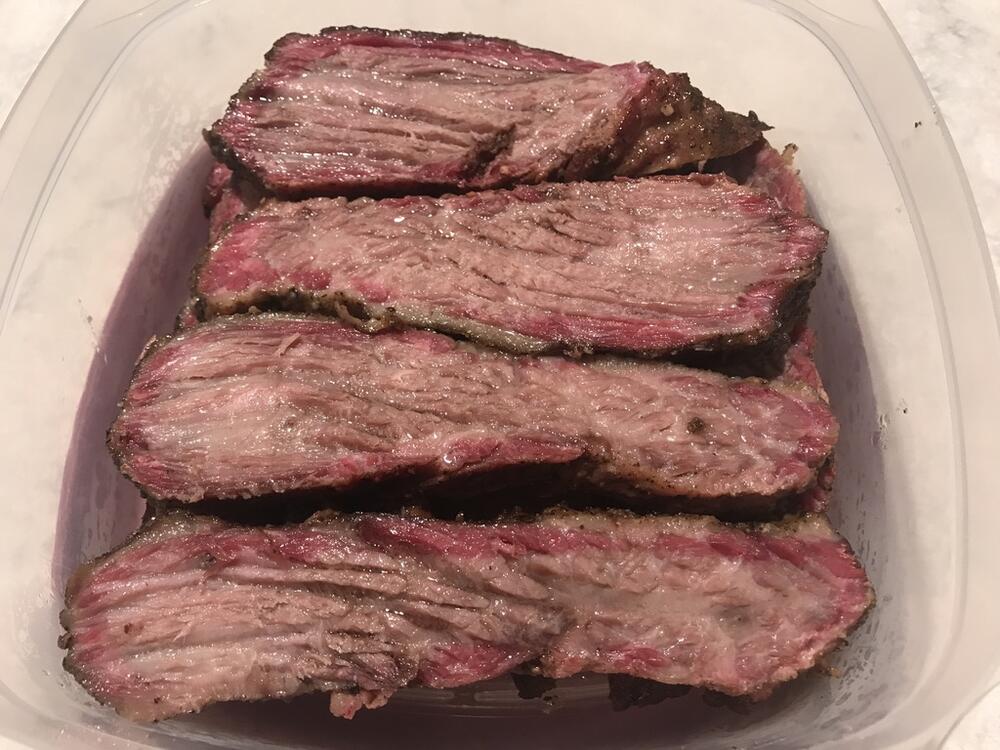
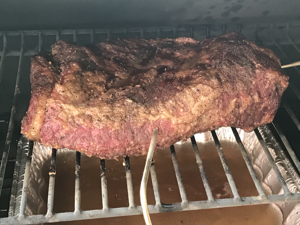
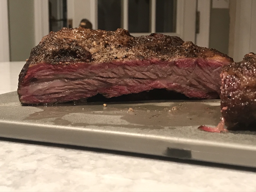
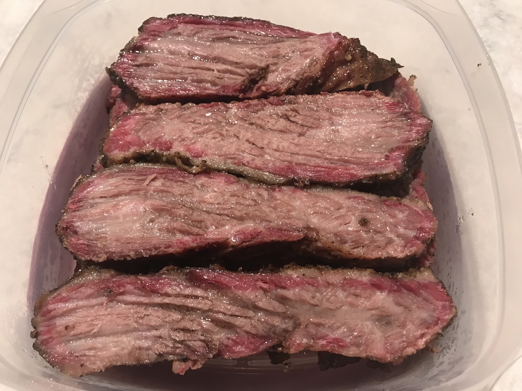
10 pointsPre-made dinner for tomorrow night's pre-ride feast. Certainly appears to be sufficiently juicy, hopefully it'll reheat acceptably.


 10 points
 -
9 pointsTonight I had a couple prime ribeyes and I did the reverse sear in the oven at 180 with a probe in the steak. I removed the steaks at 115 degrees and had a cast iron pan very hot and ready. Seared the top, bottom, and two long sides. Came out great for doneness, texture and crust.9 points
-
9 pointsNo pics. Did my first tri-tip on Labor Day. Served with smoked mac & cheese for the neighbor ladies. Who knew 3 petite senior ladies could put away so much food. Leftovers were one serving only. The tri-tip was ridiculously easy to make and had incredible flavor. I'll have to do another.9 points
-
6 pointsThe site defaulted me back to light theme after the upgrade. In other news, I am now officially blind.6 points
-
5 pointsT2 first listening impressions. wow..... erm.... wow..... erm..... wow The first thing that strikes me is marco dynamics are amazing, on recordings that are not that dynamic the amp does not exaggerate the dynamics, but on dynamic recordings like full orchestra the dynamics are so powerful but not overdone. This is backed up with bass is far more defined, less mushy, more full than my other stax amps but the bass is not not dry or hard or overblown Stereo images are more solid and tangible and more precise than any other stax amp I have, its so close to the experience my Quad 2805 speakers..... Detail is amazing, but the detail is not thrown at you and its therefore not tiring to listen to. But I do notice tape edits, dropped violin bows, musical score page turns more... but it just adds to the experience that tens of musicians in a room can't be totally silent all the time. when music gets complicated there is far less tendency for sounds to just clump together into a messy mushy ball. However you still get the feeling of musicians playing together and the detail is not analytic. The amp just says here is all the detail let it wash over you and you decide how much you want to listen into the detail and how much you want the whole music. This is the first time I have been satisfied with the bass and dynamics from my sr007a mk2. I think it shows that my stax sr007a just need as much drive as they cant get. My journey: stax srm006 (piece of mushy yet bass light and less bass the higher the volume, undynamic, undetailed, poorly constructed, stereo thick soup, gloop with the sweetness of a lemon), hi-amp alpha centauri (improvement in every way over the srm06, its an upgrade but you still feel there is music missing. Overall you get the impression is nothing special and has but poor bass, slightly deeper than the srm006, but mid and upper bass is almost non existent. Bass loss with volume is far less), blue hawaii (murders the alpha in every way but maybe slightly hard sounding for me and a bit of a tiring long term listen. It was a very enjoyable build and a considerable step up from the alpha but I rarely could relax into the music), Mini T2 (better micro dynamics, smoother and more refined more listenable than the hawaii but lacking in some drive and macro dynamics, detail and bass. I still got the feeling with it that it was struggling with the sr007s a bit) and finally the T2 (im sure I will eventually find something wrong with it... that's just the way my brain works but for now im content [which is rare])... So whats next after the T2? (other than building a second one).... Many many thanks to Kevin for the T2 and joamat for the modified T2 and mini T2, spritzer for providing the nos transistors and everyone for their encouragement and help.5 points
-
5 points
-
3 pointsVava brand air purifier, the one with UV light for bacteria. They are cheap silent so get multiples to spread around your crib. For masks look for three layer cotton preferably with pockets to allow for insertion of non woven poly propylene fabric (Etsy, Admathagifts). As for locust hords and boils I recommend Ortho Home Defense Max and a topical steroid cream.3 points
-
3 points3 points2 points2 points2 points2 points2 points2 pointsThis guy's use of the Deluge is at least demigod level - he did all audio for this in the Deluge, including mixing/mastering. And I want to know more about his video sampling technique.2 pointsTough day at work and xmas music rejuvenates. It’s like Popeye’s spinach. Don’t ask me how many hours I listened to the day after W. was re-elected.2 points2 points2 points2 pointsThe dark theme needed a swift kick in the ass, the menu pops up correctly with it now.2 points2 pointsThis is now fixed in the dark theme. New forum software version + clean install of the theme did the trick.2 pointsHail to the chief.2 points2 pointsAdding to the apocalypse documentation. Approaching noon in Mtn View. Was brighter after sunset. Keeping on eye out for boils tomorrow.
 2 points1 point1 point1 pointAlso, I really like the Bad Gear youtube channel, if anyone here doesn't know it.1 point1 point1 pointDunhill has reacquainted himself with home, after a week in North Carolina. Silver has too, but she is in a box. I've gotta brush that Pendleton blanket. Dunhill goes out of his way to be a hallway obstacle in the dark.
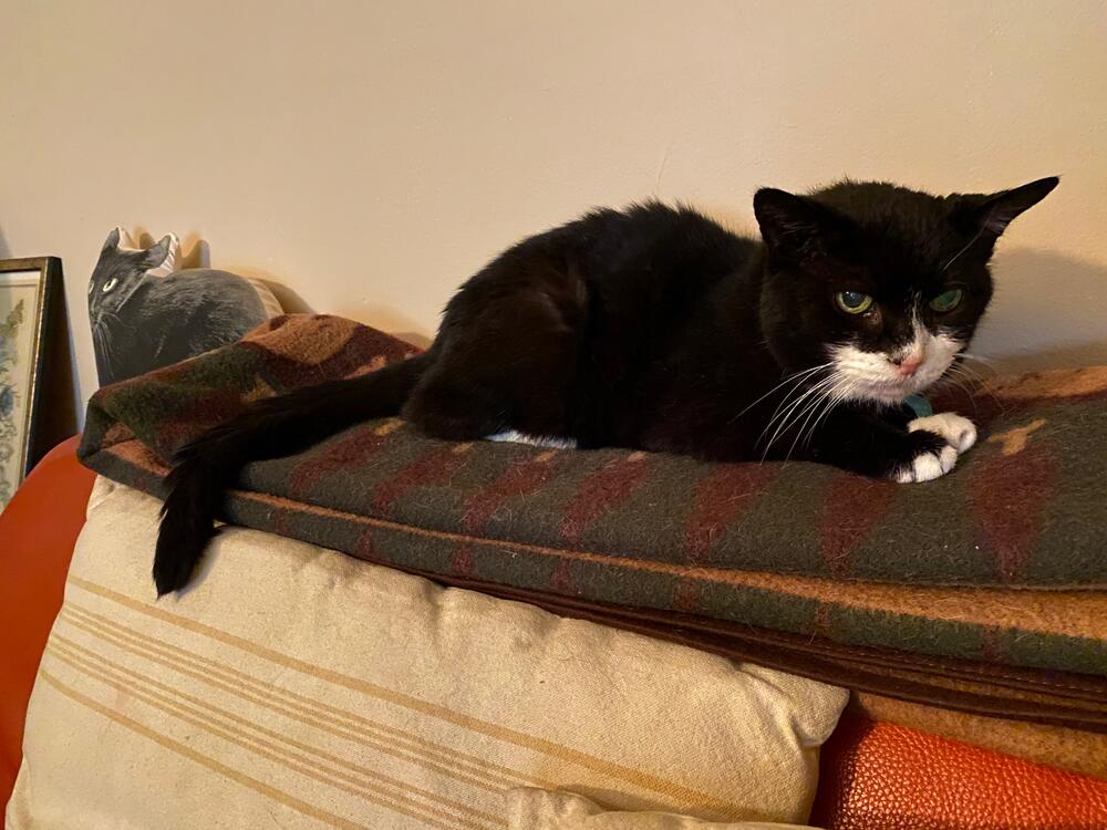 1 pointI liked this....but couldn't help thinking it was Uncle Fester on bass 😄1 point1 point1 point1 point1 pointSo far I dig it, dark pads or the ones with the cloth liner are really needed. Noticeable etch without them... with them tho a touch smoother without a massive lose in tactility. Overall pleasant, good tonality and detail with a nice stage. I'll have more in a few days once I get a chance to really listen. Comparisons to 009, 95X with Vesper and hopefully L700 Mkii if it arrives in time1 point1 pointScroll to the very bottom of the page and you will see a Theme drop down. Choose Deflection or whatever it is called now.1 point1 pointNate's gonna knock me off the head-case Strava leader board this weekend1 point1 pointPlus it comes in black! I will forward the suggestion, thanks!1 point1 pointMaybe it was triggered by me selecting an alternate image size from w/in IOS? I'll check when I get back to my phone. It's in a drawer far away at this point and I am officially lazy.1 point1 pointThe Winix 5500 seems to be the best bang for your buck. But this is Head-Case, so I'll shut up.1 pointno 5.1k series resistors on the outputs is a super bad idea. definitely bad for the headphones and a safety issue if the mosfets ever short.1 pointThis new editor is kinda weird. More like 3, but who's counting? Raymond Loewy design for Studebaker "Wagonaire" with retractable sliding rear roof section, 1963. Also, Imgur informs me that I've been on the site for 10 years as of yesterday.1 point1 point1 point1 pointI'd have to hear it to get the effect, but it sounds interesting. Both subs are the same? I've often thought about a quick 10" sub, supported by a deeper 15".1 point1 pointtry not to kill the user until AFTER they have finished paying for it Equal rights for electrons! they should be allowed to travel freely and not be constrained by insulation... If they want to travel through your heart it just their way of being loving and friendly.... they are so misunderstood.1 point1 pointNeither do I, so I listen to those who do. I suppose the other approach is to just not care about things you don't understand.1 point1 point1 pointThe haze cleared long enough to get a view of Mt Tam this afternoon.
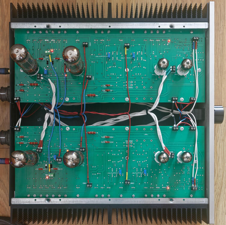
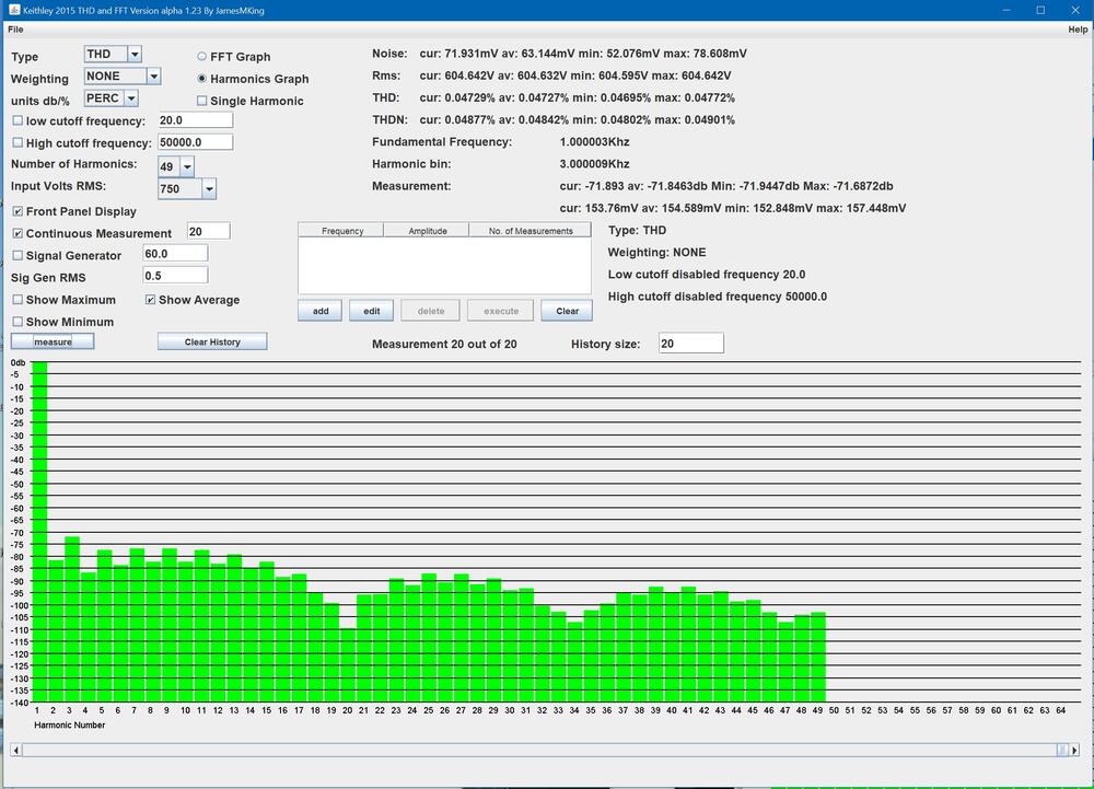
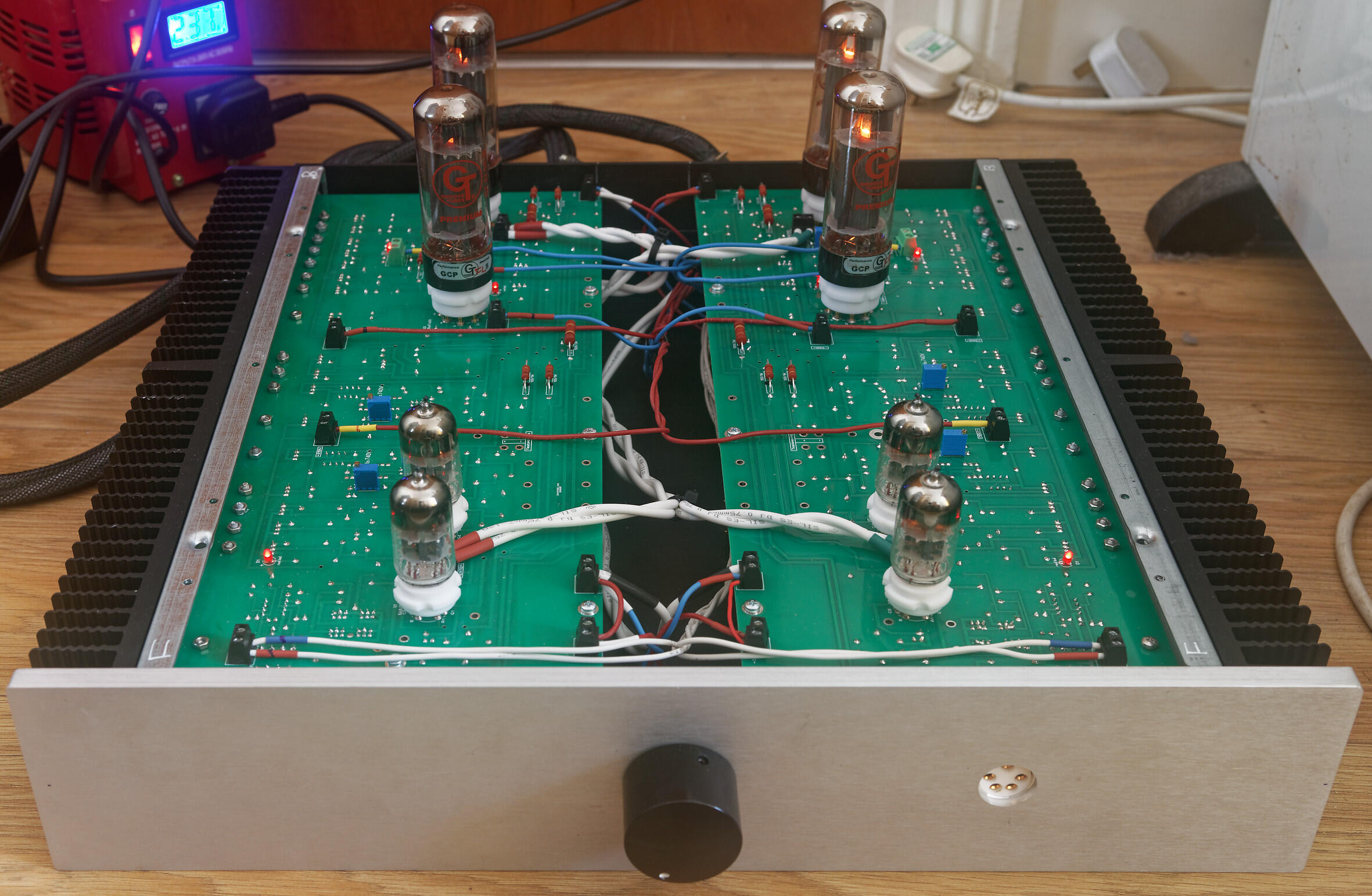
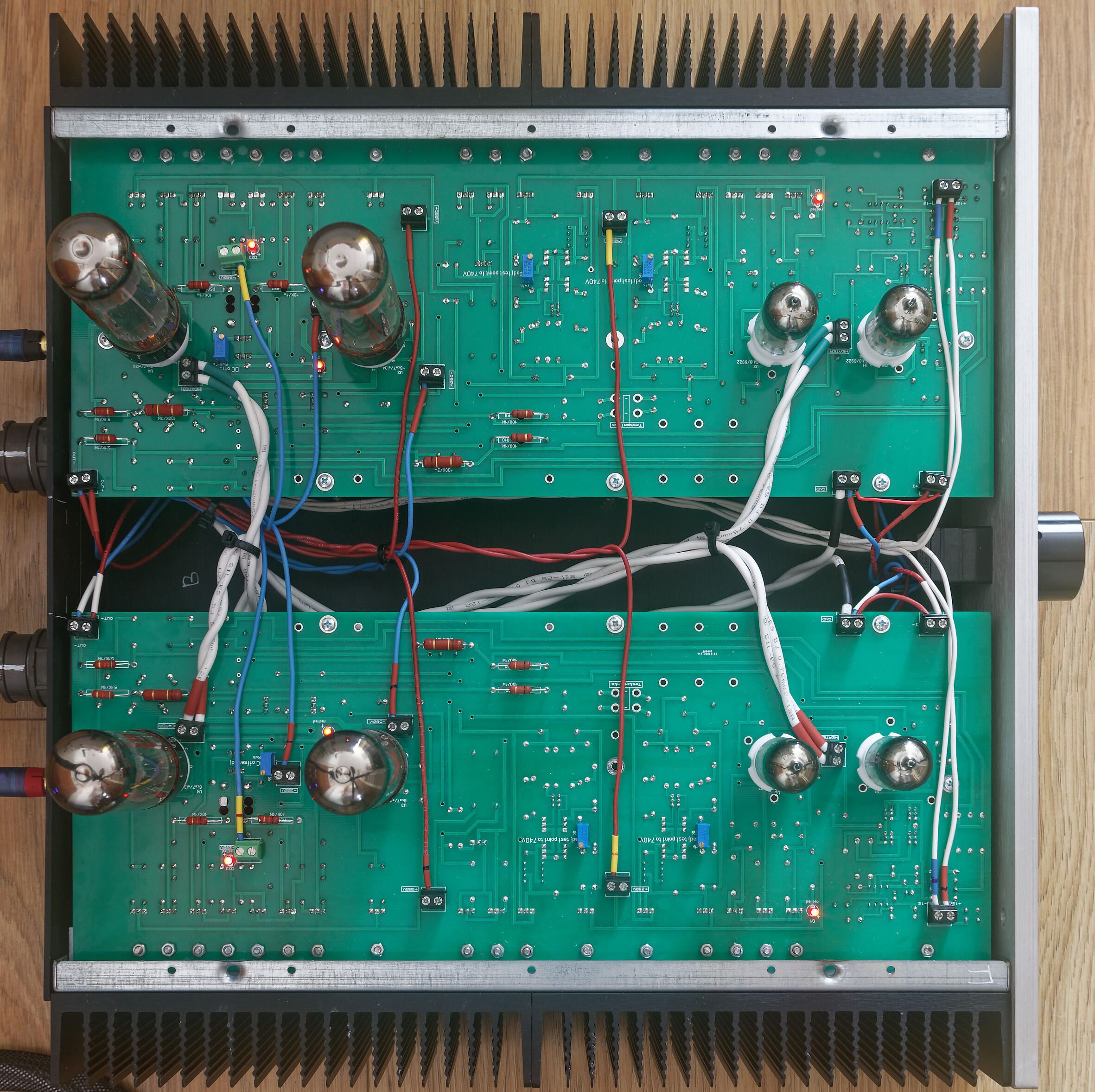
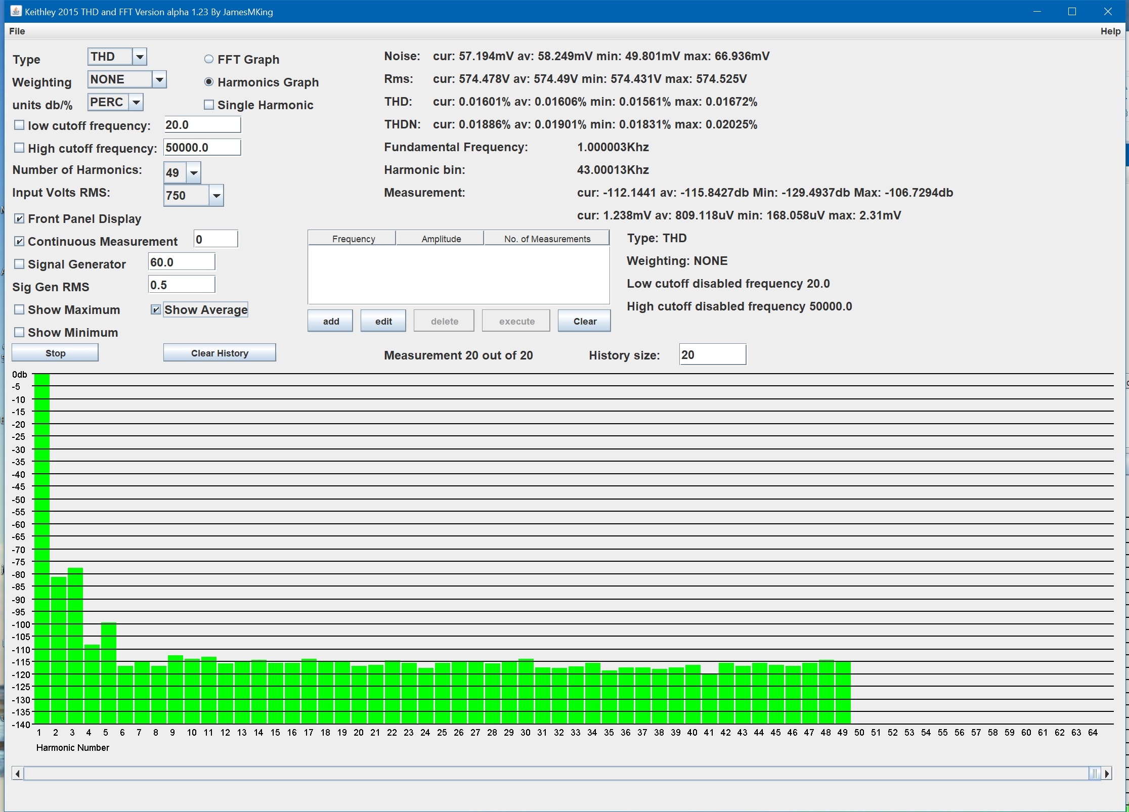
 1 point1 pointlisten to it? if you check my todo list nowhere does it say listen to it... measure it yes... listen to it? why would I do that? 🙃 latest update, internal signal wiring done (silicone not cardas - I need to buy more cardas chassis wire) and front panel completed. Both channels powered up at the same time for the first time. No drama so far. The heatsinks around the el34s runs a bit hotter than joamats mini T2. I not done any temperature checks look good. All transistors seem ok and so do the high power resistors. .6922 heater voltage is a little high at 6.35V so I will need to add some dropper resistors. All other voltages are spot on. El34 heaters are at 6.1V which is about the same level as my mini T2. I found my first issue, the DC balance between + and - halves of a channel is fine <50mv BUT the DC offset to ground started at -85V and even adjusting the offset pot all the way I only got it down to -33V. Exactly the same on the other channel due to close matching of components and matched valves. So I will need to replace the dc offset adjustment trimmers with something 2-3x the range. Anyway I know you have been waiting for the money shot: glowing leds and heaters so enjoy: Im currently going for an extended power on idle test and will be periodically checking voltages and temperatures on both the amp board and psu. If that passes it will be time to feed it some test signals... I hoping for more detail in the square waves, more dynamics in the triangle waves and smooth fatigue free sine waves. Here are the first measurements. Distortion 1Khz input Total Harmonic Distortion to 49Khz is around 0.0063% unweighted (average of 20 measurements) 2nd harmonic is around -90db and third slightly higher at -87db. The other harmonics are very low all less than -105db. total harmonic distortion plus noise is better than 0.018% (im not using shielded cables for this test AND the amp and psu do not have top lids and the cases are not grounded so the amplifier is almost certainly has better thd+n than I am measuring in this setup. At around 575V rms 5th harmonic starts to rise and at 600Vrms output all harmonis increase and odd order are higher than even order harmonics. NOTE this measurements where taken with around 35V DC offset so it is possible clipping may occur a little later with less offset... Noise, THD, THD+N and level of distortion harmonics at 575V RMS, 1Khz output: Noise, THD, THD+N and level of distortion harmonics at 600V RMS output 1Khz: The THD up to 49Khz is still less than 0.05% The amp runs quite a bit hotter than the mini T2, heatsinks near the EL34s run at 40C and power consumption is close to 205W. The mini T2 is around 153W. The power supply is also is less efficient than the golden reference HV, the 3W resistors between the ksa1156es and ksc5026 run close to 90C and dont have a lot of room around them, on one side there is a large 0.1uF 1KV film cap and on the other 5 closely packed transistors... So the T2 needs good heat sinking and the psu boards could do with lengthening a little to give the 3W resistors a little more air flow around them and drill holes under them. Update DC offset fix, The 5K pot in parallel with the 510 ohm emitter resistor gives a minimum resistance of about 461ohm which still gaves me ~ -33V offset. With the 5K pot in the middle you get around 423ohm combined resistance and ~ -85V offset. So I replaced the 510ohm with 604ohm and this gives enough adjustment range to get <1V DC offset. (I would have implemented joamats suggestion but I did not have any 10K pots)
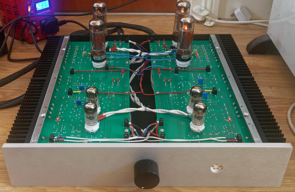

 1 point1 pointMy black cats who have been stepped on because I mistook them for puddles of shadow beg to differ.1 point1 pointI am back and while the previous debates cleared up differences between class A and AB, I have some further remarks. In order to make these remarks I will use available information through [electronics-tutorials . ws] which I will link to down bellow. If not for anything new, then this entry is in large for myself and possibly other who read and have the same questions / concern as I do, and remember, this is for educational purposes. *** I started this thread with a question: Why no KG class AB ? because my perspective was that if done right, class AB could sound as good as class A but retain a better efficiency. Not that I made that clear in the first entry, at least it was in the back of my mind and I wanted to check for explanations from other more enlightened head-case members who could explain things in a way I could not. I am still learning and the information which I have come over in the past few day is an eye opener. Yes yes I know, for most of you the information I will present is old news, no brainer or perhaps jaw dropping. No matter, I've had a blast, learned things I did know would transpire and also made it very clear how things should be done from now on. So lets get going. Edited reply's for the convenience of this entry, but you can always go up and read the full statement(s). JimL; 1) - So basically, until Mark Levinson and Krell came along, pretty much all amplifiers were class AB because nobody thought that there was a big enough market to support a class A commercial amp. Class AB was considered the best compromise between cost, efficiency and sound quality. It was never considered the best, just that Class A was considered too expensive. 2) - The first Mark Levinson Class A amp was rated at 25 watts (but was reportedly class A down to 2 ohms, at which point it was a 100 watt amp), was mono, and was big, heavy and cost a few thousand dollars - I think you could have bought over 100 NAD3020 integrated amps for the same money, and the 3020 was stereo, had roughly the same power rating, and included a phono section. But, it turned out that there was a market for it, and Krell came out with stereo class A amps that had more power and generated more heat. And it's gone on from there. The limiting factors for speaker amps is basically how much power do you need and how much money (and size, and heat) do you want to spend getting it. 3) - For non-electrostatic headphone amps it is significantly different. Here, you only need a few watts at most, into higher impedances than speakers have. So low to moderate voltages (say 15 volts at most)and relatively low currents (an amp or so at most). Based on specs, the least efficient non-electrostatic headphone is the HFM Susvara, and 5 watts into that should produce 120 dB, which is enough to give you hearing damage in minutes if sustained. So in theory, a class A headphone rated at 5 watts into the Susvara's impedance should do the trick. Which means that an amp that draws 25-30 watts from the wall should be able get you close to the threshold of pain In that case, there isn't a lot to be gained by dropping back to class AB. That said, some cheap headphone amps ARE run in class AB because the manufacturer doesn't want to lay out money for heatsinks. Every penny counts. 4) - One other detail is how the push-pull output stage is biased. This is basically what determines whether an amp is Class B, AB or A. For class B, the output stage is biased at zero, meaning with no signal there is no current running through the output devices. 5) - In class AB, there is some current running through the output devices with no signal, but when a signal is sent through the amp, each of the two output devices only reproduce half plus a bit more of the output, and the combination of both devices is needed to produce the whole signal. In reality the output devices are turning on and off during the output, which can produce crossover distortion, which is a transient that occurs when the device turns on or off. The problem is that this distortion actually gets worse as a proportion of the output was you go to lower power, until you get down to the point where the signal is small enough that the turn on and turn off does not occur. 6) - Now with most music other than the compressed crap that some modern producers are putting out (i.e. loud all the time), the fact is that much of music is at a volume that is 10-20 dB below maximum, so that an amp is usually running a 1-10% of max power. 7) - Now for true class A, there is enough current running that both devices output some signal current at all times. In theory this should only matter for music peaks. In reality, since active devices (tubes, transistors) are more linear in the middle of their operating range rather compared to their limits, this decrease distortion at all levels. So far so good right. I sat down an made a cup of coffee with a thought in the back of my mind: Remember, KG Dynalo and Dynahi is push-pull (PP) class A amplifier. The PP class A was new to me because I viewed class A as single ended and push-pull as class AB. Class A: – The amplifiers single output transistor conducts for the full 360o of the cycle of the input waveform. Class B: – The amplifiers two output transistors only conduct for one-half, that is, 180o of the input waveform. Class AB: – The amplifiers two output transistors conduct somewhere between 180o and 360o of the input waveform. Clarification: AB which use a minimum of two transistors conduct 0o to 180o for the positive cycle and 180o to 360o for the negative cycle. Class A: The most commonly used type of power amplifier configuration is the Class A Amplifier. The Class A amplifier is the simplest form of power amplifier that uses a single switching transistor in the standard common emitter circuit configuration as seen previously to produce an inverted output. The transistor is always biased “ON” so that it conducts during one complete cycle of the input signal waveform producing minimum distortion and maximum amplitude of the output signal. This means then that the Class A Amplifier configuration is the ideal operating mode, because there can be no crossover or switch-off distortion to the output waveform even during the negative half of the cycle. Class A power amplifier output stages may use a single power transistor or pairs of transistors connected together to share the high load current. This is the simplest type of Class A power amplifier circuit. It uses a single-ended transistor for its output stage with the resistive load connected directly to the Collector terminal. When the transistor switches “ON” it sinks the output current through the Collector resulting in an inevitable voltage drop across the Emitter resistance thereby limiting the negative output capability. The efficiency of this type of circuit is very low (less than 30%) and delivers small power outputs for a large drain on the DC power supply. A Class A amplifier stage passes the same load current even when no input signal is applied so large heatsinks are needed for the output transistors. However, another simple way to increase the current handling capacity of the circuit while at the same time obtain a greater power gain is to replace the single output transistor with a Darlington Transistor. These types of devices are basically two transistors within a single package, one small “pilot” transistor and another larger “switching” transistor. The big advantage of these devices are that the input impedance is suitably large while the output impedance is relatively low, thereby reducing the power loss and therefore the heat within the switching device. It is possible to obtain greater power output and efficiency than that of the Class A amplifier by using two complementary transistors in the output stage with one transistor being an NPN or N-channel type while the other transistor is a PNP or P-channel (the complement) type connected in what is called a “push-pull” configuration. This type of power amplifier configuration is generally called a Class B Amplifier and is another type of audio amplifier circuit that we will look at in the next tutorial. Class B: To improve the full power efficiency of the previous Class A amplifier by reducing the wasted power in the form of heat, it is possible to design the power amplifier circuit with two transistors in its output stage producing what is commonly termed as a Class B Amplifier also known as a push-pull amplifier configuration. Push-pull amplifiers use two “complementary” or matching transistors, one being an NPN-type and the other being a PNP-type with both power transistors receiving the same input signal together that is equal in magnitude, but in opposite phase to each other. This results in one transistor only amplifying one half or 180o of the input waveform cycle while the other transistor amplifies the other half or remaining 180o of the input waveform cycle with the resulting “two-halves” being put back together again at the output terminal. Then the conduction angle for this type of amplifier circuit is only 180o or 50% of the input signal. This pushing and pulling effect of the alternating half cycles by the transistors gives this type of circuit its amusing “push-pull” name, but are more generally known as the Class B Amplifier. The Class B Amplifier has the big advantage over their Class A amplifier cousins in that no current flows through the transistors when they are in their quiescent state (ie, with no input signal), therefore no power is dissipated in the output transistors or transformer when there is no signal present unlike Class A amplifier stages that require significant base bias thereby dissipating lots of heat – even with no input signal present. So the overall conversion efficiency ( η ) of the amplifier is greater than that of the equivalent Class A with efficiencies reaching as high as 70% possible resulting in nearly all modern types of push-pull amplifiers operated in this Class B mode. The Class B amplifier circuit above uses complimentary transistors for each half of the waveform and while Class B amplifiers have a much high gain than the Class A types, one of the main disadvantages of class B type push-pull amplifiers is that they suffer from an effect known commonly as crossover distortion. Hopefully we remember from our tutorials about Transistors that it takes approximately 0.7 volts (measured from base to emitter) to get a bipolar transistor to start conducting. In a pure class B amplifier, the output transistors are not “pre-biased” to an “ON” state of operation. This means that the part of the output waveform which falls below this 0.7 volt window will not be reproduced accurately as the transition between the two transistors (when they are switching over from one transistor to the other), the transistors do not stop or start conducting exactly at the zero crossover point even if they are specially matched pairs. The output transistors for each half of the waveform (positive and negative) will each have a 0.7 volt area in which they are not conducting. The result is that both transistors are turned “OFF” at exactly the same time. A simple way to eliminate crossover distortion in a Class B amplifier is to add two small voltage sources to the circuit to bias both the transistors at a point slightly above their cut-off point. This then would give us what is commonly called an Class AB Amplifier circuit. However, it is impractical to add additional voltage sources to the amplifier circuit so PN-junctions are used to provide the additional bias in the form of silicon diodes. The Class AB Amplifier: We know that we need the base-emitter voltage to be greater than 0.7v for a silicon bipolar transistor to start conducting, so if we were to replace the two voltage divider biasing resistors connected to the base terminals of the transistors with two silicon Diodes. The biasing voltage applied to the transistors would now be equal to the forward voltage drop of these diodes. These two diodes are generally called Biasing Diodes or Compensating Diodes and are chosen to match the characteristics of the matching transistors. The Class AB Amplifier circuit is a compromise between the Class A and the Class B configurations. This very small diode biasing voltage causes both transistors to slightly conduct even when no input signal is present. An input signal waveform will cause the transistors to operate as normal in their active region thereby eliminating any crossover distortion present in pure Class B amplifier designs. A small collector current will flow when there is no input signal but it is much less than that for the Class A amplifier configuration. This means then that the transistor will be “ON” for more than half a cycle of the waveform but much less than a full cycle giving a conduction angle of between 180o to 360o or 50% to 100% of the input signal depending upon the amount of additional biasing used. The amount of diode biasing voltage present at the base terminal of the transistor can be increased in multiples by adding additional diodes in series. Class B amplifiers are greatly preferred over Class A designs for high-power applications such as audio power amplifiers and PA systems. Like the class-A amplifier circuit, one way to greatly boost the current gain ( Ai ) of a Class B push-pull amplifier is to use Darlington transistors pairs instead of single transistors in its output circuitry. This section is the most interesting and important one. For Class A amplifier operation the switching transistors Q-point is located near to the center of the output characteristic load line of the transistor and within the linear region. This allows the transistor to conduct for the complete 360o so the output signal varies over the full cycle of the input signal. The main advantage of Class A is that the output signal will always be an exact reproduction of the input signal reducing distortion. However it suffers from poor efficiency, because to bias the transistor in the center of the load line there must always be a suitable DC quiescent current flowing through the switching transistor even if there is no input signal to amplify. For Class B amplifier operation, two complimentary switching transistors are used with the Q-point (that is its biasing point) of each transistor located at its cut-off point. This allows for one transistor to amplify the signal over one half of the input waveform, while the other transistor amplifies the other half. These two amplified halves are then combined together at the load to produce one full waveform cycle. This NPN-PNP complimentary pair is also known as a push-pull configuration. Because of the cut-off biasing, the quiescent current is zero when there is no input signal, therefore no power is dissipated or wasted when the transistors are in the quiescent condition, increasing the overall efficiency of a Class B amplifier with respect to Class A. However, as the Class B amplifier is biased so that the output current flows through each transistor for only half of the input cycle, the output waveform is therefore not an exact replica of the input waveform since the output signal is distorted. This distortion occurs at every zero-crossing of the input signal producing what is generally called cross-over distortion as the two transistors switch “ON” between themselves. This distortion problem can be easily overcome by locating the biasing point of the transistor slightly above cut-off. By biasing the transistor slightly above its cut-off point but much below the centre Q-point of the class A amplifier, we can create a Class AB amplifier circuit. Then the basic purpose of a Class AB amplifier is to preserve the basic Class B configuration while at the same time improving its linearity by biasing each switching transistor slightly above threshold. End of article entry. Conclusion - Bias, bias and some more bias. So now that we have a grasp of the difference between class A, B and AB, how do we tie together class AB and push-pull class A ? We do so by adjusting the bias to the transistors quiescent point or Q-point to the linear portion. The transistor is a linear device in the active region and nonlinear in its cutoff and saturation region. - That's it. This is the answer and "secret" wo why Kevin Gilmore use push-pull class A in his dynamic headphone amplifiers. "For now I have seen the light". We can ofc achieve the same performance via single ended but we are power limited, by using several transistors in a chain we can obtain a much higher output power but maintain in class A the whole time. That's it. I don't think I have anything els to add here. I totally get why KG is only interested in push-pull class A. - Oneminde Sources: 1. https://www.electronics-tutorials.ws/amplifier/amp_5.html 2. https://www.electronics-tutorials.ws/amplifier/amp_6.html 3. https://www.electronics-tutorials.ws/amplifier/class-ab-amplifier.html
 1 point1 pointWell, I think things are a bit more complicated than that. For speaker amps, you generally need a lot of power unless you have very efficient speakers, e.g. horns, which is another topic altogether. We're talking about 50-100 watts per channel or more. So the amp needs to produce 40 volts peak for a 100 watt amp, and on the order of 10 amps if we have a 4 ohm speaker. Now, a class A push-pull amp has a maximum theoretical efficiency of 50% (single ended class A has a max efficiency of 25%), so that means it runs at 100-200 watts/channel all the time. This means lots of tubes (old days) or lots of heatsink for solid state. All this means lots of heat and lots of money (and that doesn't even include the cost of running the damn things). So basically, until Mark Levinson and Krell came along, pretty much all amplifiers were class AB because nobody thought that there was a big enough market to support a class A commercial amp. Class AB was considered the best compromise between cost, efficiency and sound quality. It was never considered the best, just that Class A was considered too expensive. The first Mark Levinson Class A amp was rated at 25 watts (but was reportedly class A down to 2 ohms, at which point it was a 100 watt amp), was mono, and was big, heavy and cost a few thousand dollars - I think you could have bought over 100 NAD3020 integrated amps for the same money, and the 3020 was stereo, had roughly the same power rating, and included a phono section. But, it turned out that there was a market for it, and Krell came out with stereo class A amps that had more power and generated more heat. And it's gone on from there. The limiting factors for speaker amps is basically how much power do you need and how much money (and size, and heat) do you want to spend getting it. For non-electrostatic headphone amps it is significantly different. Here, you only need a few watts at most, into higher impedances than speakers have. So low to moderate voltages (say 15 volts at most)and relatively low currents (an amp or so at most). Based on specs, the least efficient non-electrostatic headphone is the HFM Susvara, and 5 watts into that should produce 120 dB, which is enough to give you hearing damage in minutes if sustained. So in theory, a class A headphone rated at 5 watts into the Susvara's impedance should do the trick. Which means that an amp that draws 25-30 watts from the wall should be able get you close to the threshold of pain In that case, there isn't a lot to be gained by dropping back to class AB. That said, some cheap headphone amps ARE run in class AB because the manufacturer doesn't want to lay out money for heatsinks. Every penny counts. For electrostatic headphones, it is different again, stat headphones have very high impedances, so you need very high voltages but relatively minuscule currents - a few mA. because you need to have high voltage - the Stax amps generally have +/-350V supplies, the KG amps generally run +/-350V to +/-450 volts, the Stax and DIY T2 run +/-500V supplies. Now the Stax amps run around 5-7 mA/output device, the KG amps up to 20 mA/output device, and there are 2 output devices per channel. So given that, the Stax amps draw about 40-55 watts from the wall, the KG amps run about 140 watts to more than 200 watts (the latter from a DIY T2, which also has 8 tube heaters using energy).1 point


Important Information
By using this site, you agree to our Terms of Use.
Account
Navigation
Search
Configure browser push notifications
Chrome (Android)
- Tap the lock icon next to the address bar.
- Tap Permissions → Notifications.
- Adjust your preference.
Chrome (Desktop)
- Click the padlock icon in the address bar.
- Select Site settings.
- Find Notifications and adjust your preference.
Safari (iOS 16.4+)
- Ensure the site is installed via Add to Home Screen.
- Open Settings App → Notifications.
- Find your app name and adjust your preference.
Safari (macOS)
- Go to Safari → Preferences.
- Click the Websites tab.
- Select Notifications in the sidebar.
- Find this website and adjust your preference.
Edge (Android)
- Tap the lock icon next to the address bar.
- Tap Permissions.
- Find Notifications and adjust your preference.
Edge (Desktop)
- Click the padlock icon in the address bar.
- Click Permissions for this site.
- Find Notifications and adjust your preference.
Firefox (Android)
- Go to Settings → Site permissions.
- Tap Notifications.
- Find this site in the list and adjust your preference.
Firefox (Desktop)
- Open Firefox Settings.
- Search for Notifications.
- Find this site in the list and adjust your preference.