Leaderboard


Popular Content
Showing content with the highest reputation on 09/29/21 in all areas
-
9 points
-
5 pointsWow, somehow I missed this. Thanks for the birthday wishes. Had to teach my two labs on Friday and then Karen took me out for dinner. That is a bigger deal than it sounds as she hates going out to dinner.5 points
-
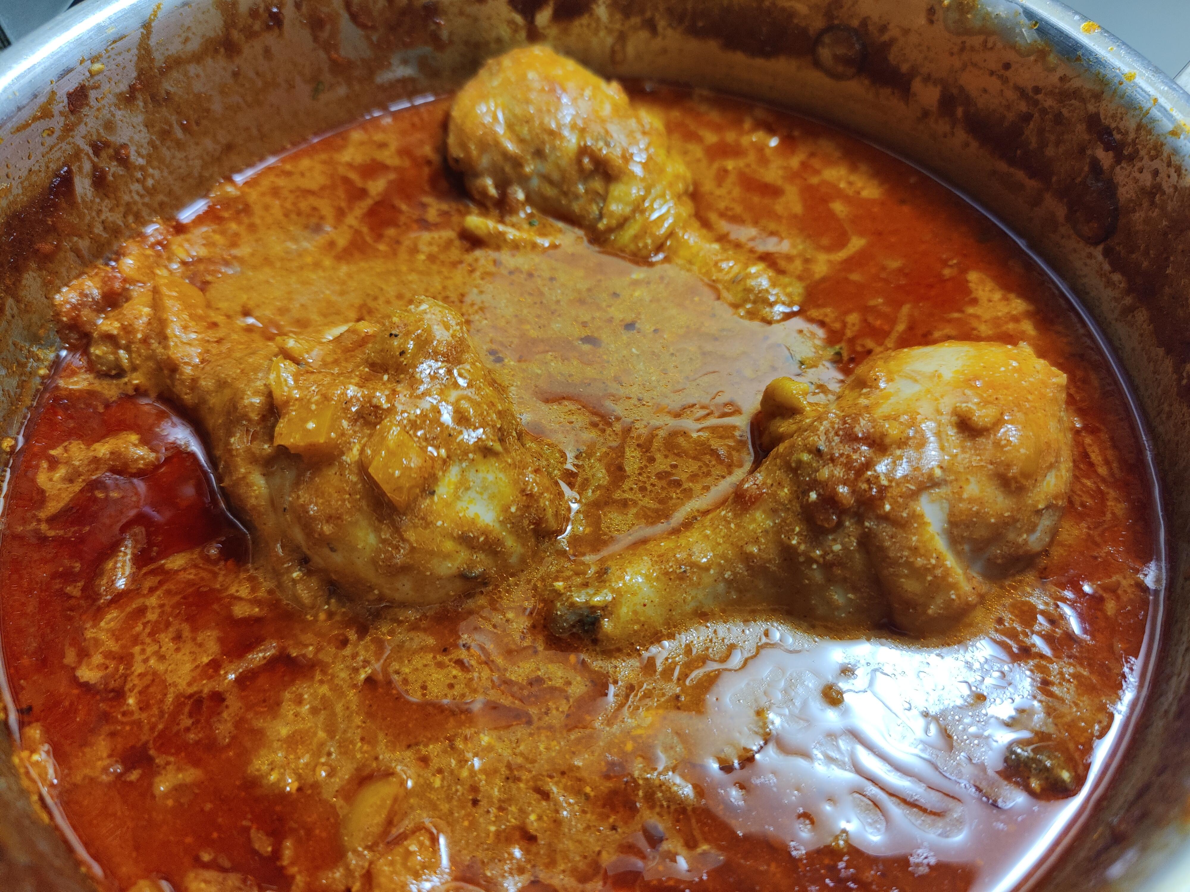
3 pointsSome very relaxing vertically integrated burger and bacon food pr0n NTTATWWT3 points
-
3 points
-
3 points
-
3 points
-
3 points
-
2 points
-
Bach: The Art of Fugue, BWV 1080 Les inAttendus, Vincent Lhermet, Marianne Muller, Alice Piérot 2021 Example:2 points
-
1 point
-
1 pointDid she make you wear a bib? 😜 Seriously though, the other day I was drinking iced tea, and dribbled on myself 2 or 3 times. This 60+ shit ain't for the faint of heart. When my TICE stops workin', I'm checkin' out! (Not that I need it that often)1 point
-
1 point
-
1 pointWhat else would it be? "Just Google the words 'curry' and 'banana'and you'll get over 2,000,000 hits. I think it's a British colonial era traditional thing to eat sliced banana alongside curries." https://www.mumsnet.com/Talk/am_i_being_unreasonable/865535-To-eat-banana-with-my-curry1 point
-
1 pointI think Rob's dick's place in history is secure. Guys just remember everyone doubted Google and their modular phones.1 point
-
1 point
-
This is both absolutely amazing and utterly terrible. Tears for Fears were always miles above most 80s synth pop, in all aspects. Their songwriting, musicianship and lyrics have stood the test of time for nearly 4 decades now. Roland and Curt are both impressive live performers, even if they don't particularly like playing out. (Not entirely true, they love playing but they hate touring.) In this performance from 2014 they absolutely nail all of their classic hits and a couple album tracks. The problem is that the video director (I refused to call him a cinematographer) that Spotify hired needs to be taken out back by the chemical shed and shot. The bright lights on behind the band are a terrible idea. It's not artistic. It's blinding to both the studio and video audience. The use over overly long lenses, entirely too shallow a depth of field and constant rack focusing isn't artistic either. It's absolute crap. It's like if a new photographer who just got his first 50mm F/1.4 and refuses to stop it down ever was put in charge here. All of the shots from behind the audience, using their out of focus blobs as a framing device aren't artistic. They are endlessly frustrating tripe. The reaction shots of the audience, while a staple of every live performance ever, are executed so poorly here it's mind boggling. It's not easy to film a live music performance, but it's not exactly rocket surgery, either. Point camera at performers. Keep performers in focus. When editing, try to switch to performer doing most important thing (solo, singing, etc.) Maybe include some audience b-roll. Light the stage so that performers are visible, distracting background details are not, and NO ONE IS BLINDED (except for key moments.) The director of this video failed on every front. They should be sentenced to a life of only working on dish soap commercials. In spite the wretched production, I watched the entire video. I have always had mixed feelings about Tears For Fears. Their music is amazing, but for me it's a time capsule to a chunk of the 1980s where I suffered extreme trauma due to a confluence of terrible things happening at once. I've never fully processed the aftermath and I'm not sure I will be able to. Tears for Fears brings me right back some of the worst moments of my life, but I still love their music. They still have it as musicians, as well.1 point
-
1 pointA question to one of the forum administrators: is it a good idea to move my posts starting on the 25th of September to a separate thread? Maybe called "KSA-5 inspired amplifier builds". I think I saw a few posts where some forum members wanted to keep this thread a more 'pure' clone build. Thanks.1 point
-
1 pointGetting a little glimpse at an alternative world - Match Game 2008 pilot with Norm MacDonald, Sarah Silverman, Rashida Jones, etc.1 point
-
Re: Shatner.....everything is fun, but NOTHING will ever beat this:1 point
-
Makes sense. I can see why you were easily impressed!1 point
-
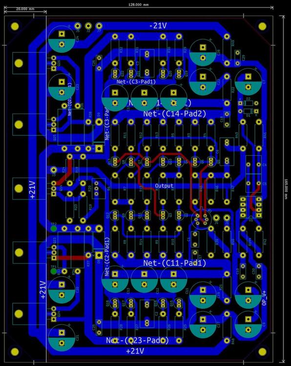
1 pointIndeed, the routing of the HT-rails is somewhat complicated, but my initial goal was to stick to the exact sequence of components as indicated by the original layout. I agree, that tidying up here and re-arranging to be more streamlined might be the way to go. The effects on the performance will probably be negligible. Regarding the arrangement of power output devices, the effect of mixing them up might not be worth the effort. If it saves some space I might consider this. Output protection circuitry is definitely a must! However a pure power on delay is too little. I was thinking of incorporating a protection circuit as outlined by AMB in his Epsilon12 muting delay & DC offset protection circuit. However, I will offer up a separate power supply for this with rather weak filter caps to ensure that the relays will drop off immediately after power off. Pulling current from the amps heavily buffered HT-rails is not a good idea in my opinion and fixing this issue by introducing a breaker contact parallel to the AC input power switch is not practical. Here in Germany we are required to break 230V power with both power leads (phase + neutral) and normal switches rated for mains voltage never come with more than two poles. Another option that I might include in the additional pcb for DC-protection is the addition of a DC blocking capacitor in the audio input path. Yes, I know there are many opinions on this topic out there. But after reading up on the topic in my favorite books "Small Signal Audio Design" and "Audio Power Amplifier Design" by Douglas Self, one sentence by Doug stayed in my memory: "In some respects, any DC-coupled power amplifier is an accident waiting to happen." He has also done respectable research on the effects of all kinds of electronic components and comes to the conclusion that coupling or DC blocking capacitors have no effect on linearity as long as they are installed in the low voltage or input side of an amplifier. Anyway, I want to give DC blocking a try and if I personally cannot hear a difference to the DC coupled version, then I will rather be on the safe side ... I like my headphones very much! And as a final note, I will definitely give the mods by my name twin above a go and see if I can even hear a difference!! Cheerio, Alex.1 point
-
1 pointa few impressions from the SoCal meet: no. 1 " Audeze CRBN , silky, great low end for an estat, impressive soundstage, faster than the lcd-5 but without the same tactile feel. Sounded MUCH better out of the mjolnir audio than the Z10e. Very different than Stax, and I really enjoyed these. I may not even need to hear the sr-x9000 before deciding to put my order in. Sounds like the waitlist is until Jan … crazy." no. 2 "The best sound for me were the Audeze CRBN's. These are my next dream headphones. They sound totally different from Stax, and have their own sound signature that I really liked. They were musical and had a visceral slam/punch I haven't heard in my own collection of electrostatics. I've never heard the HE-90's, but the CRBN's sound like what I dream a HE-90 would sound like." no. 3 "Unfortunately I don't think they bring anything to the table. As a big 009 fan, I think if you are making a non typical estat-like estat, you better have something special to justify the specific amplifier requirement. This definitely doesn't have either the 007 magic or the 009's extreme detail and lightness. I might need some more time with it but so far I haven't found anything impressive from them." no. 4 "listened to the CRBN after auditioning the LCD-5. Solid headphone, although I preferred the HFM Shangri-la Jr. due to its superior soundstaging and overall refinement. Probably my favourite headphone that I heard today! I detected a bit of grain in cymbals on the CRBN, although the audition was too brief to make any definitive statements. Bass was definitely above average on both the Audeze and HFM by 'stat standards. Some dynamic compression seems to be a fact of life with this technology vis-a-vis planars, but the Shangri-la Jr. does offer more resolution than even the Susvara, and I'm intrigued for sure. Will listen to both again tomorrow and update my impressions." no. 5 "CRBN (some un-obtainium set up). After hearing these I understand why some people warship e-stats. The CRBNs have a delicate presentation, but they don’t ever sound thin or lacking in body. The overall frequency response is very similar to the LCD-5, but the presentation is a lot different. The bass is excellent in texture and level, easily better than the Susvara. Not as punchy as the LCD-5 though. Midrange is equal to or better than anything here. More body to the vocals than the Susvara. Treble, comparing here again to the Susvara, the Susvara are pretty magical, but I like the texture of the CRBN a little better. The soundstage on these is larger, open and layered in a way where I could easily forget I was wearing headphones. The build quality and comfort here again are equal to or better than anything. As far as pure aesthetics, these are the best looking headphones I have ever seen. In person they are stunning." no. 6 "I had a short opportunity to A/B test CRBN and 009s on Mytek & BH. (Also heard CRBN on Mjolnir Audio but I felt the A/B test was much more interesting.) CRBN sounds very tonally correct, polite, but didn’t carry the sparkles nearly as much. Sound stage is smaller than 009s. I felt CRBN is more similar to Elite and Utopia than to 009s. I personally would pick 009s every time over CRBN. I didn’t get to test bass heavy songs at all, which I heard is what CRBN excels at. What a pity." no. 7 "But now for me and the one BURNING question I had was how does CRBN sound on the Blue Hawaii Special Edition? As some one who still owns and enjoys the original 009 my curiosity was peaked! And honestly... for starters I feel like CRBN does everything the original 009 set out out to, it retains that insane sense of speed and detail I love about 009 BUT has a slightly denser tone with noticeably stronger bass with all the detail and transparency I've come to expect. It's sound stage is a little more intimate too and all in all while I still love the original 009's lovely tone, exceptional nuance and delicacy. I could 100% see my-self picking up CRBN as a compliment for when I want that extra bit of weight, heft and intimacy without any lose in the speed or detail that I love about Electro Stats! But overall I feel that CRBN really captures and delivers the true spirit of Audeze! Powerful, detailed TRUE to life BASS! A natural weighty mid range with amazing speed and clarity that alongside with crystal clear highs are all presented within an outstandingly cohesive and precise sound stage. I for one can't wait to get a little more time with BHSE and CRBN! It's likely going to become my new favourite thing to hear at each show until I'm ready to pick up a set for myself!" no. 8 "Overall a fluidic, semi-sweet / modestly dry (in a good way), linear sound with the full FR represented. Bass texture was spot on but overall leans ever so slightly towards a brighter signature not far off from Stax SR-009. Soundstage was great as well, but may be a small step behind Stax Lambda series in that regard. Sense of PRaT was nearly impeccable, though drums may not hit with quite as much authority as a well driven dynamic or planar headphone (something Mark Cohen of Audeze also confirmed). These pull it off so nicely that one may not even notice any shortcomings whatsoever, and can do almost any genre with finesse and seemingly left over headroom to boot. This paired exceptionally well with what I believe was the Mjolnir Audio Carbon e-stat energizer. For a comparison to the SR-009 I would have to do more testing, but I would say the SR-009 has superior sense of resolution, speed, depth and emotional / visceral quality. Not necessarily better overall, just different." no. 9 "Holy moley this was the headphone of the show for me. I'm an electrostatic headphone fan, and the CRBN's bass surprised me. I find the SR-009/009S to be too bright for me and I much prefer the Dan Clark Audio VOCE over them. I don't know how the Mjölnir Audio Carbon sounds since the only thing usually at these shows is the Blue Hawaii, but the CRBN sounded pretty solid out of it. Volume-wise, I needed to turn the volume knob quite a ways for the CRBN, so either the Carbon doesn't output a lot of power (which I doubt since it's made by spritzer/Mjölnir Audio), or the CRBN isn't very sensitive (whose technical specification is unlisted on Audeze's website). There was good texture and presence in the bass region, more so than the other estats I've heard, but it didn't overwhelm the midrange. The midrange had excellent clarity and timbre overall, but was a tad bit warm-sounding to me from the bass region. Unlike any other estat I've heard, the bass seemed to take the main stage away from the midrange, as the mids seemed laid-back in comparison (which reminds me a bit of the 007 MKI from memory). The frequency response sounded more linear/smooth overall compared to what I'm used to hearing from the SR-404. The treble, like a lot of estats, was silky smooth and retains a lot of detail overall. Image separation paired with the Carbon sounded excellent, which is another feature I find estats to do well compared to other transducer types. The soundstaging seemed a bit small compared to the 009/009s/VOCE to me, and was more rounded than the SR-Lambda series. Compared to what I'm used to hearing with the Lambda series, the images were spaced more around my head versus left/right and vertical, which I appreciate. Also like most estats, I was able to turn up the volume really high without experiencing any fatigue. The other transducer types don't seem to be able to replicate this effect, and I have no idea why. Comfort-wise, these rock. Audeze's headband on the CRBN is quite comfortable. Paired with the supple leather earpads, the CRBN fits snugly, but not too snug on my head. The oval-shaped earcups fit on my head pretty well even with glasses on. At 300 g, this thing is insanely light! The "cube" pattern on the earcups' grill is also pretty unique-looking. I feel like I've seen this pattern somewhere else, but I can't put my finger on it at the moment. The strain relief parts from the earcup look more sturdy than those of STAX."1 point
-
1 pointThe complexity of power traces looks excessive to me and suggests that an improvement could be made. If this was my board, I would try to shake it a bit, simplify, streamline, and make it more elegant. As an idea, you can try a different order of output transistors - instead of NPN-NPN-Thermal-PNP-PNP, something like NPN-PNP-NPN-PNP-Thermal, with power rails, the output trace and the ground running parallel to the edge of the board. This will bring in a different layout, which may (or may not) be helpful. Unless you plan to use some kind of off-board headphone protection, it would make sense to put the relay back. If you're not religious about the schematic, I'd suggest making the relay work for headphone protection, not just for turn-on delay. The amp seems to be reliable, but if you can avoid ruining some expensive headphones, why skip it? And of course - what would you expect - it would be great to make it possible to implement my mods (described above) on the PCB. It only takes two extra resistors and two small capacitors per channel, but the results are totally worthwhile.1 point
-
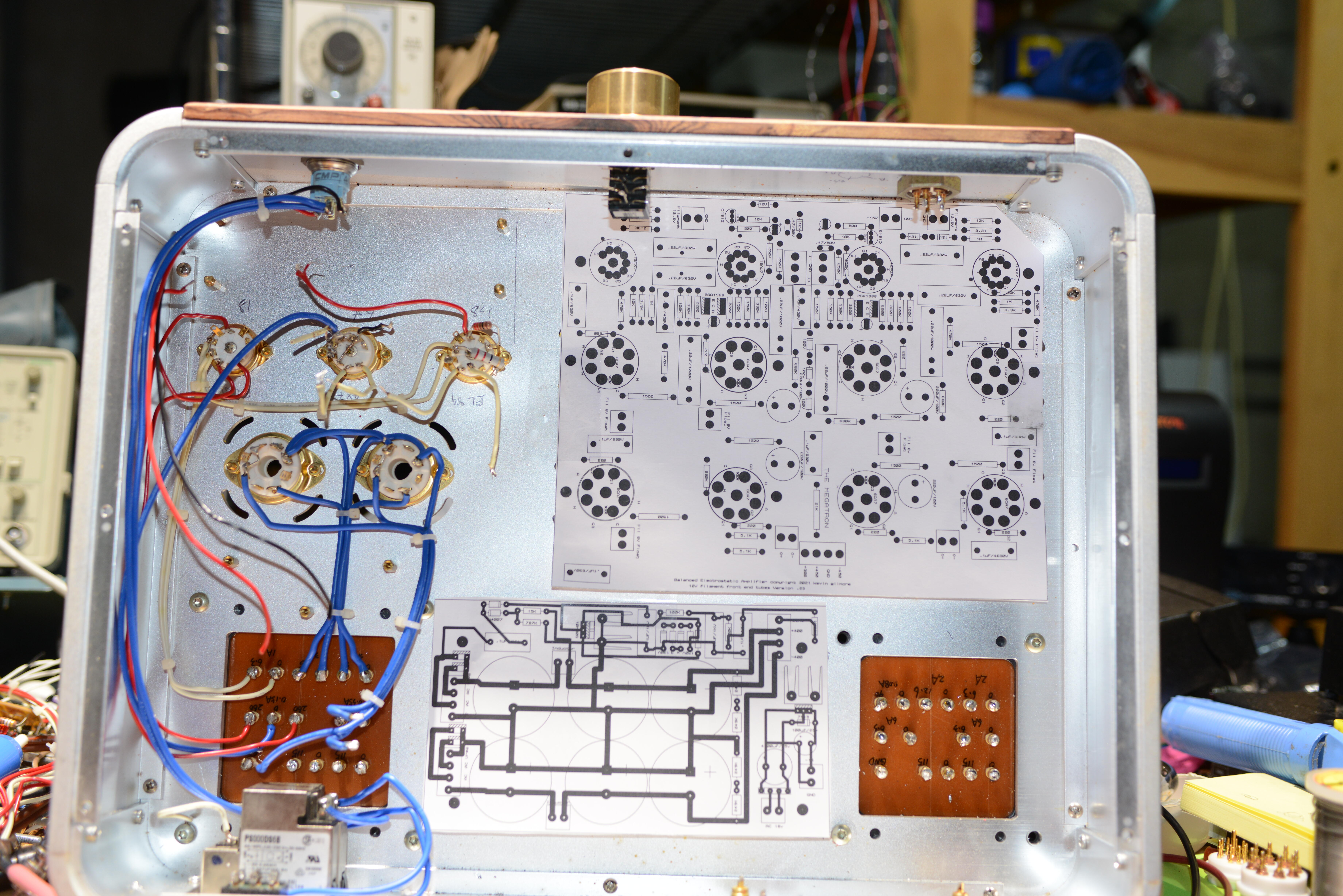
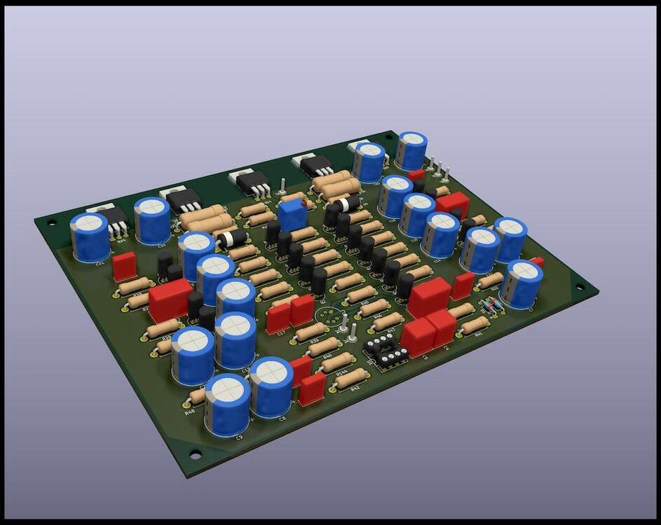
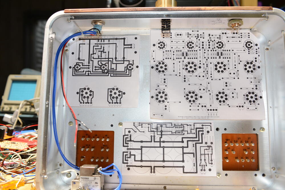
1 pointHey folks, here is a first view on my take of this amplifier. I want to be able to attach the power transistors on one side via an L-bracket to a single heat sink. The power distribution sequence layout was kept in place but of course I had to do a little re-arranging. The original input stage is more or less unchanged. Both the top and the bottom layers have copper fills for the ground plane. I omitted the relay circuits as I plan to do a separate pcb for this. The project was done in kicad. I redrew the schematic and created a fresh pcb. Just to be clear: I do not intend to make money off this and will post all source files free whenever the project has turned out to be a success. Kudos to everyone for the excellent work and efforts previously put into this project! I hope I can somehow contribute with my ideas. I would be very interested in your comments - many thanks in advance! Cheers, Alex.
 1 point
 -
1 point
-
1 point
-
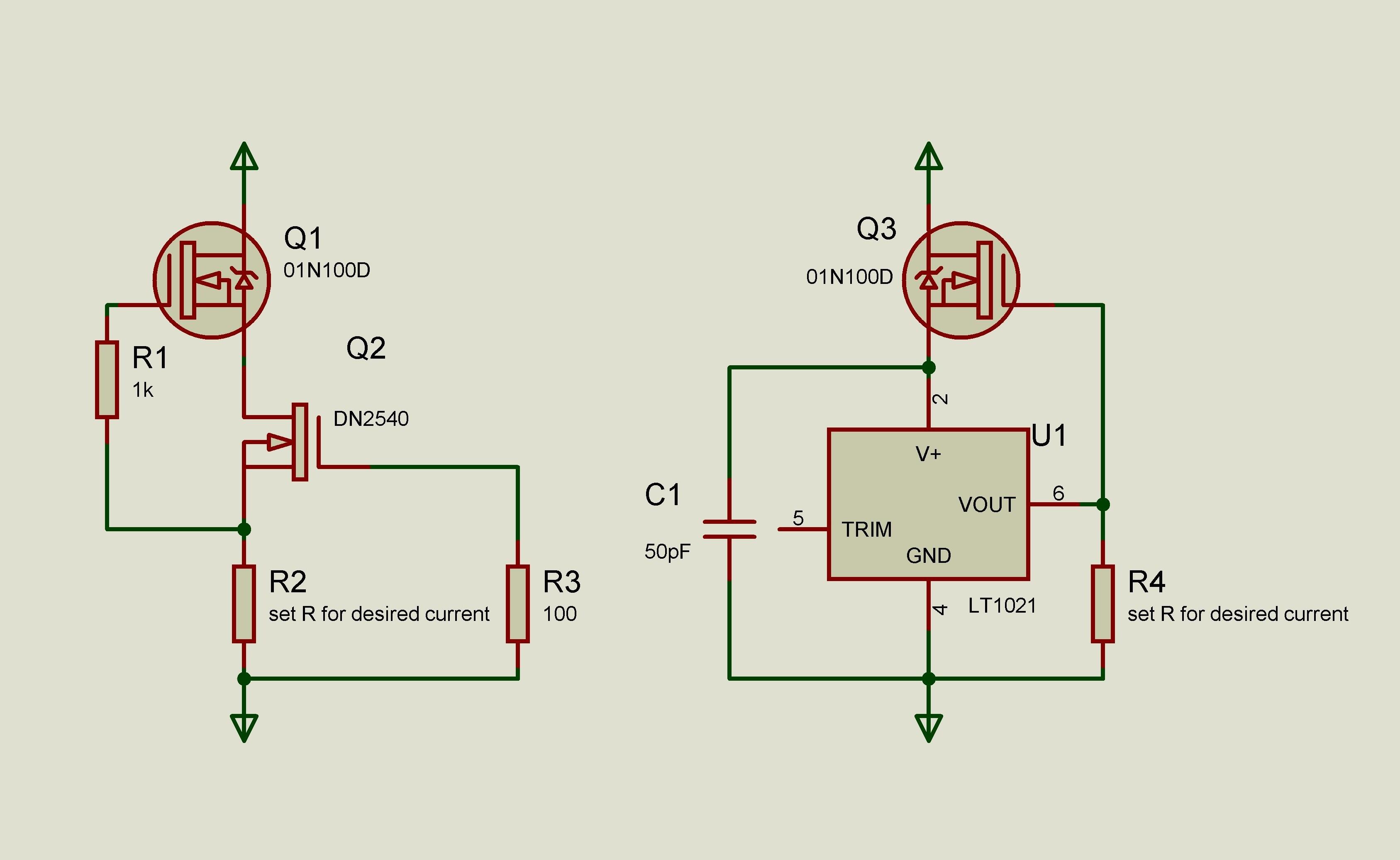
1 pointI use/have used those CCS. Good for +/-500V. I’ve replaced 2SA79/2SK216 with KSA1220/KSC2690. Looks like KSA1220 is ended, but TTA004/TTC004 should be fine.
 1 point
 -
1 point
-
1 point
-
1 point
-
1 point
-
1 point
-
1 point
-
1 point
-
1 point
-
1 point
-
1 point
-
1 point
-
1 point
-
1 point
-
1 point
-
1 point
-
You might end up with a soft start into the first C to protect the rectifier - and clearly the capacitor too!. Sort of timed relay shorting a resistor between rectifier and first C once the rectifier is nice and warm and the capacitor is charged via the limiting R. Or a MOSFET or similar device instead of a relay. What transformer is needed depends on the resistance of the inductor, the ripple on the first C (~3V p-p), and other resistive losses in the rectifier and winding resistances of the transformer itself. You could lose ~40V all told.1 point
-
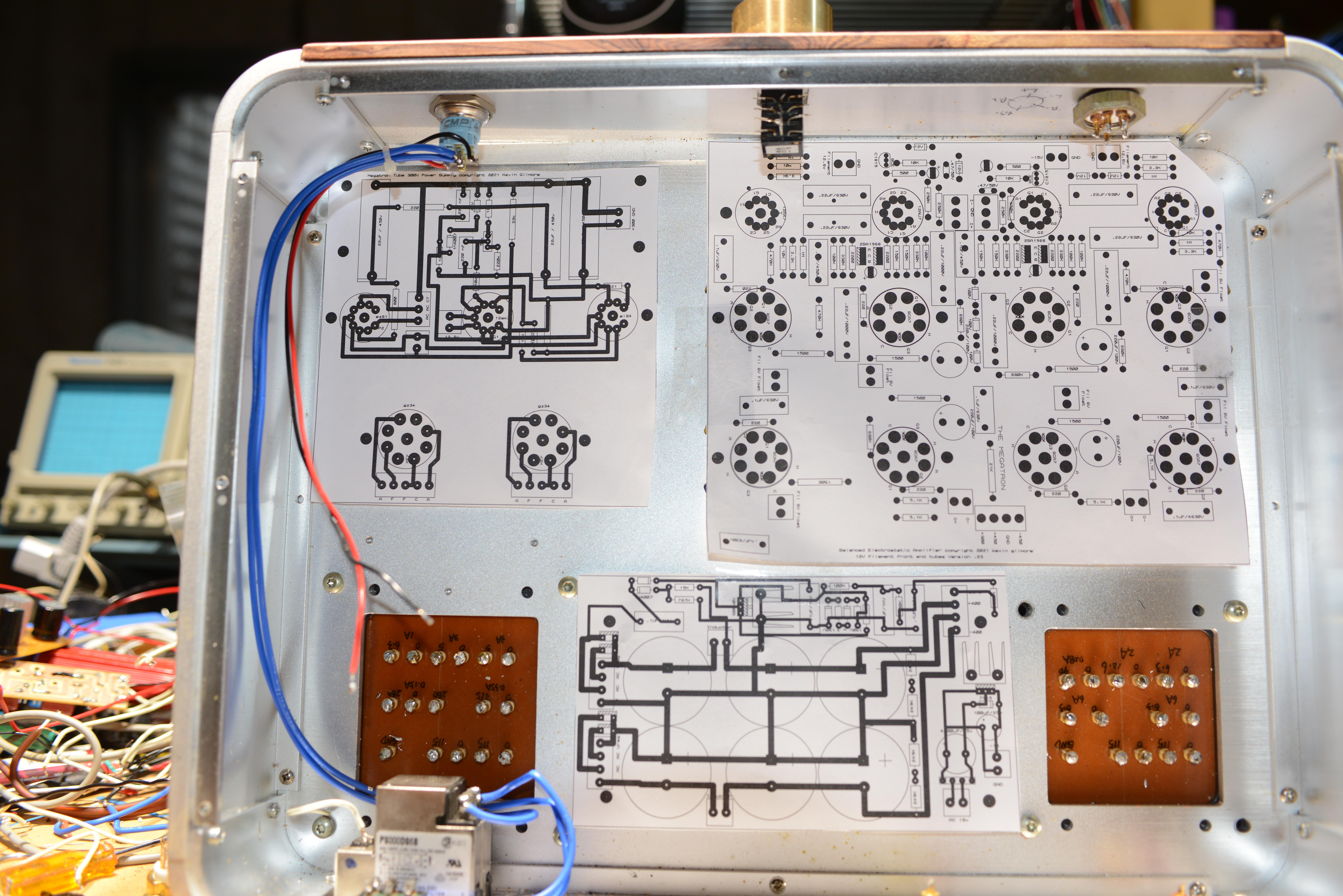
So this is what its going to look like when its done. And Hammond is willing to do the custom transformers. With a price that matches the complexity. Anyone with experience with tube rectifier power supplies driving 5 Henry inductors?
 1 point
 -
hey joamat wanna make a couple of test boards before real money is spent?
 1 point
 -
This was only on the one which I repaired for tkam, but I couldn't really tell much difference between them. I think tkam liked the zf better.1 point
-
1 pointThis answer makes no sense, as hfe is the forward current gain of a BJT transistor. LSK389 is a pair of JFETs that have no appreciable gate current, so hfe is not applicable here. Instead, the letter specifies the drain saturation current group: The drain saturation current is the current that flows through JFET when you short gate to source and apply the specified voltage (here, 10V) between source and drain. The parameter has wide dispersion in the normal manufacturing process, so each manufactured JFET is measured and marked according to its saturation current. I have not seen LSK389 without a letter - are they genuine? According to the datasheet, every transistor should be marked with a letter:1 point
-
1 pointThank you! The final mod, that of the front end, is only slightly more complicated. Here is the updated schematic with both mods: The list of changes vs. the original schematic: Replace R1, R2, R6, R7 with 100 ohm resistors Replace R5 and R8 with 332 ohm resistors Replace R9, R10, R11, R12 with 274 ohm resistors Replace R16 and R17 with 22 ohm resistors Replace R19 with a 562 ohm resistor (reuse one of R5/R8) Replace R23 with a 1 Megohm resistor Replace R24 with a 68pF 50V NP0/C0G ceramic capacitor Replace R33, R34, R35 and R36 with 0.22 ohm 2W or 3W resistors Replace R37 and R38 with one 47 ohm resistor connected between bases of Q23/Q24 and Q25/26. Make sure to connect the new resistor correctly - see the photo below - or your output transistors are at risk. Replace R47 with a 3.92k resistor Remove C2 and C3 Add a 4.7nF film capacitor and a 47 ohm resistor, connected in series, between the collectors of Q2 and Q3. Add another 4.7nF film capacitor and a 47 ohm resistor, also connected in series, between the collectors of Q7 and Q8. Place the new parts on the underside of the board if you like. Repeat for the other channel. That's it! The list of parts required to modify two channels: 8x 0.22 ohm 2W or 3W resistors 4x 22 ohm resistors 6x 47 ohm resistors 8x 100 ohm resistors 8x 274 ohm resistors 4x 332 ohm resistors 2x 562 ohm resistors (not needed if you can reuse R5/R8) 2x 3.92k resistors 2x 1 Megohm resistors 2x 68pF 50V capacitors, NP0/C0G ceramic or mica 4x 4.7nF film capacitors Some 18 AWG single core insulated wire and 2x 10 ohm 2-3W resistors for the output RL network As resistors's names are not marked on the board, here is a photo showing what to replace with what. Note that the additional parts from step 12 above are not shown - they are under the PCB. After assembly, take the usual precautions before powering the amplifier up, as if it were a newly assembled board. Turn the bias adjustment trimpots all the way counterclockwise, connect a current limited +/-21V power supply with the current limit set at 0.5A per rail. With power on, check the output for a possible oscillation, then adjust the bias and re-check for oscillations. The bias level needs to be at about 20mA per transistor - with 0.22 ohm emitter resistors, it corresponds to 4mV between the test points, which should be easy to measure with a DVM. Higher bias levels are possible, but the distortion will be slightly higher. Let the amplifier warm up for 10-15 minutes and readjust the bias - it should go down as the output transistors warm up. As with any feedback amplifier, capacitive loads may affect stability. In my testing, the amplifier remained stable with capacitive loads of up to 100nF. Consider adding the usual RL network between the output of each channel and the load to ensure stability. Make 20-30 turns of 18 AWG single core insulated wire on a 1/2 inch (12mm) former - a Sharpie will work - to make an air core inductor like this: then connect a 10ohm 2-3W resistor in parallel to it.1 point
-
1 pointI completed the full modification (output stage and front end) on both channels and listened to the amp briefly. The headphones were Grado GS1000 and Sennheiser HD595, the 8ohm speaker were B&W 602.5 floorstanders. The amplifier performed very well in each case and sounded immaculate. It is a HUGE upgrade over the original and over the output stage mod alone. I compared it against Musical Fidelity X-CANv8, and they performed equaly well. I took some measurements. Here it is delivering 1W and 5W with an 8ohm load: Here is the performance of the fully modified KSA-5 into a 32 ohm load: and into 100ohm:1 point
-
1 pointI built my KSA-5 clone back in 2013 (see my post dated August 9, 2013 in this thread on page 8) but was never quite satisfied with it. I made every effort to make it look good and perform well, and it was well within the original KSA-5's specs. Yet, although it worked well with my 32ohm Grado headphones, it could not compete, in my subjective opinion, with Musical Fidelity's X-CANv8. Connected to a pair of 8ohm speakers, the clone would become rather confused with anything but simplest music. Because of this, the amplifier fell into disuse and was gathering dust on my rack. Until this weekend. This weekend, I finally got around to make KSA-5 work for me. I kept the overall topology and the PCB, only changing some passive parts. The results are quite remarkable: The original KSA-5 was rated for 5W into 8ohm with THD<0.5%. Before modification, my clone gave 5W into 8ohm with THD @1kHz of 0.18%, well within the specs. The revised clone delivers 5W into 8ohm with 0.0015% THD, an improvement of more than two orders of magnitude. The original KSA-5 was advertised to deliver THD<0.03% into 100ohm load, although the brochure did not give the signal level for this performance. Assuming the same output voltage as for 5W into 8ohm, about 6.3Vrms @ 1kHz, my unmodified clone demonstrated THD of 0.02%, again within the specs. The revised clone drives a 100ohm load to the same level with 0.0017% THD, an improvement of more than an order of magnitude. The modified channel sounds very well, clear and transparent. I still need to complete the second channel and do some real listening. I will post the revised schematic with some explanations, as well as additional measurements, in this thread.1 point