

Leaderboard
-
n_maher
Administrators23Points27489Posts -
Hopstretch
High Rollers13Points16800Posts -
Voltron
High Rollers12Points34563Posts -
Aura
High Rollers11Points6886Posts




Popular Content
Showing content with the highest reputation on 05/25/20 in Posts
-
5 points
-
5 points
-
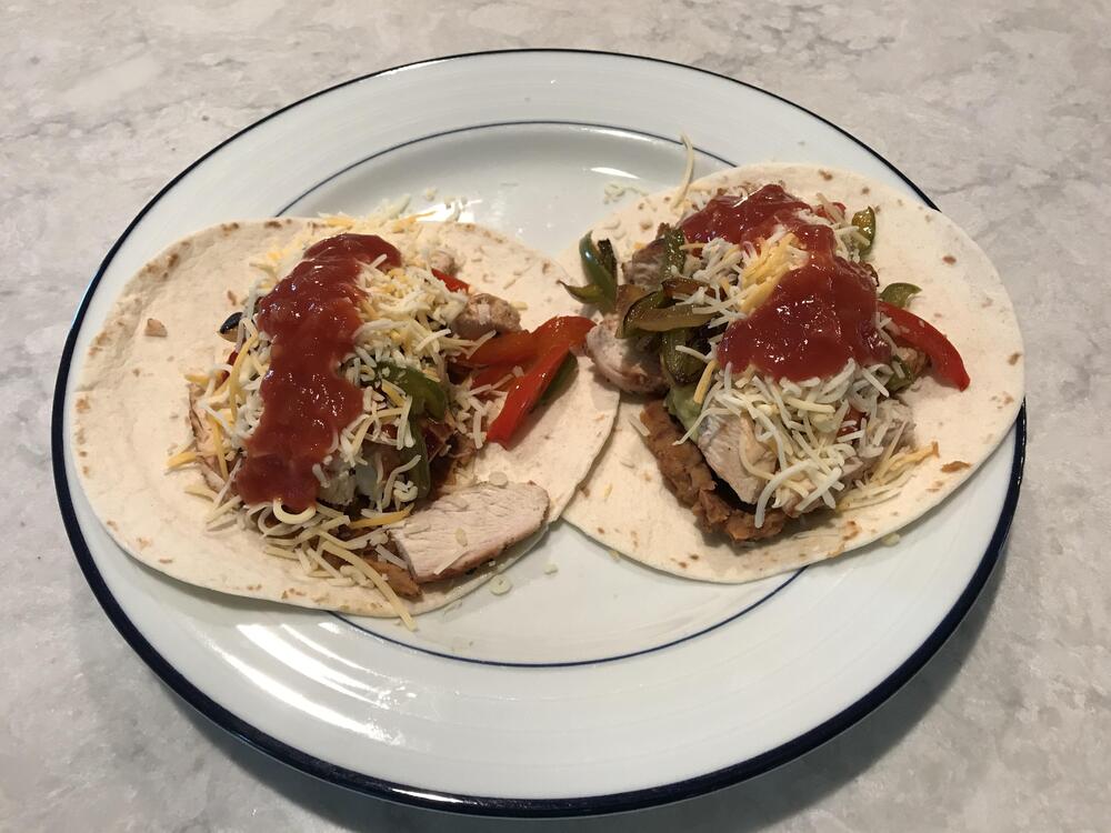
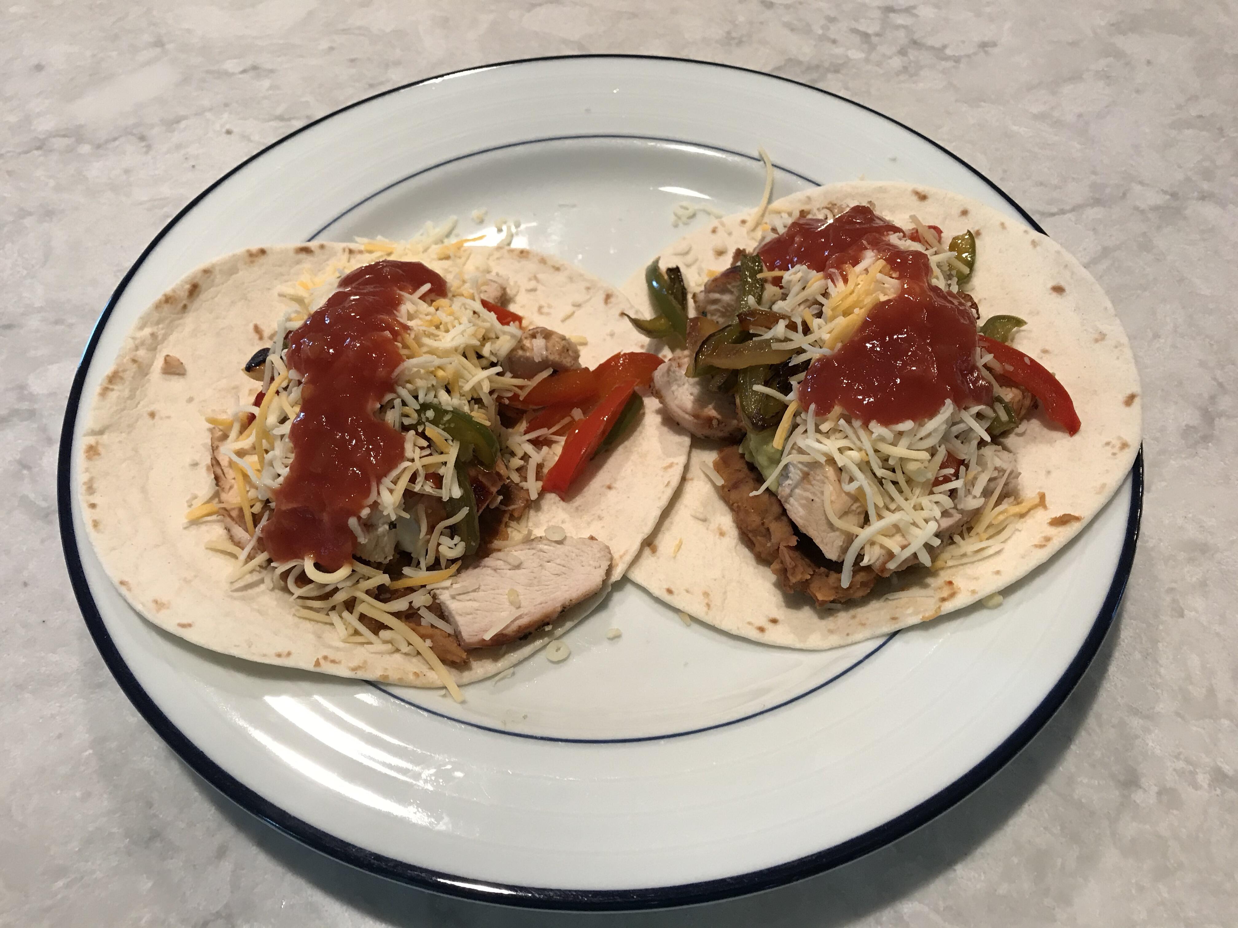
5 pointsFajitas: 1. Lime marinated chicken 2. Peppers and onions 3. Homemade refried beans 4. Sour cream 5. Guac 6. Salsa 7. Cheese Delicious.
 5 points
 -
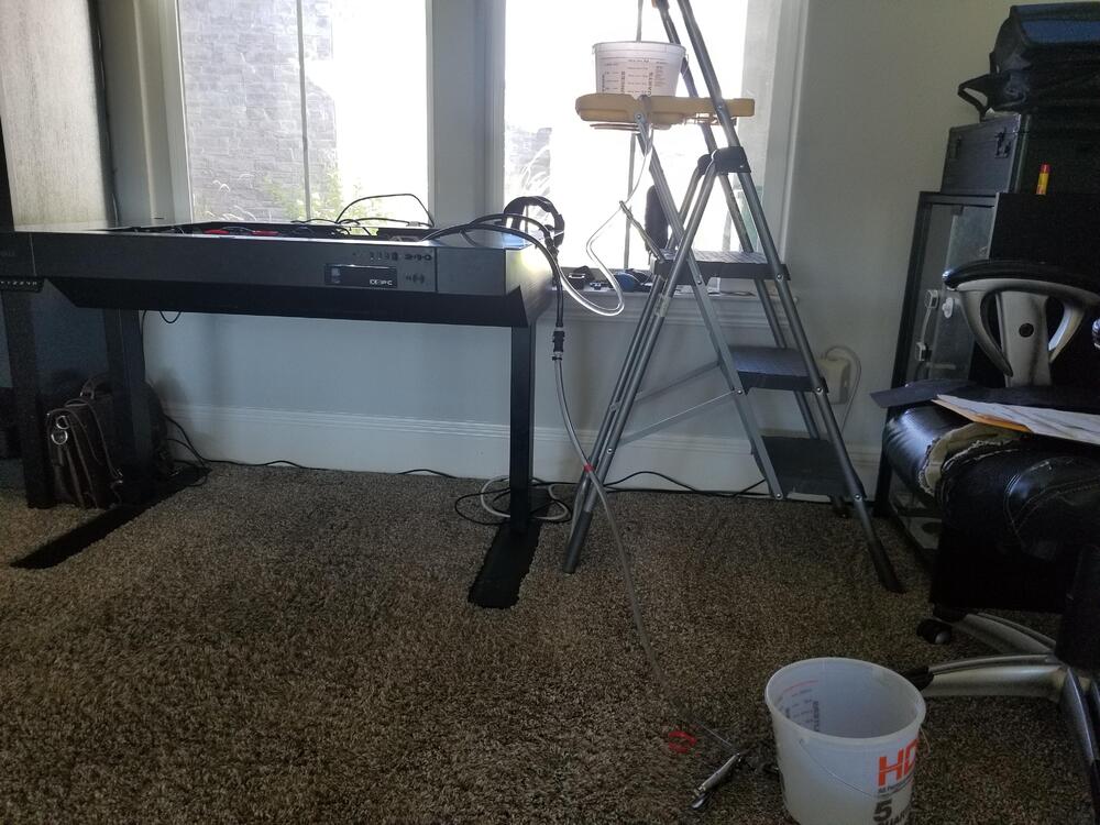
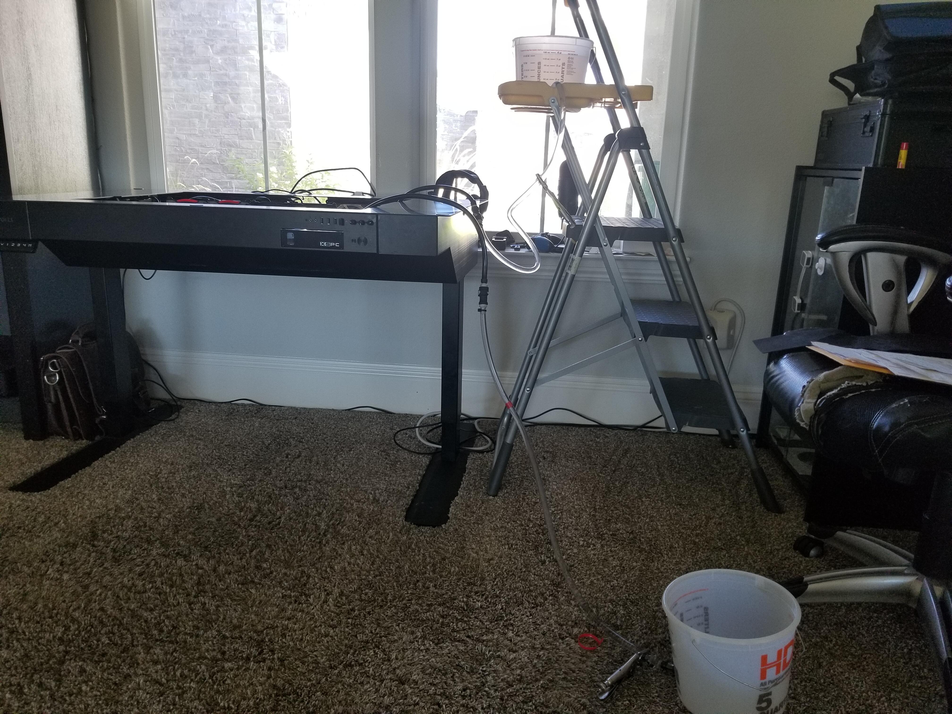
4 pointsTwo bucket method of water change out for custom pc liquid cooling. Extra 50 in 2 sets of qdcs, tubing, 2 connectors and 2 buckets. Cuts time down to less than 5 minutes and doesn't put any air in the circuit, so no de-airing needed.
 4 points
 -
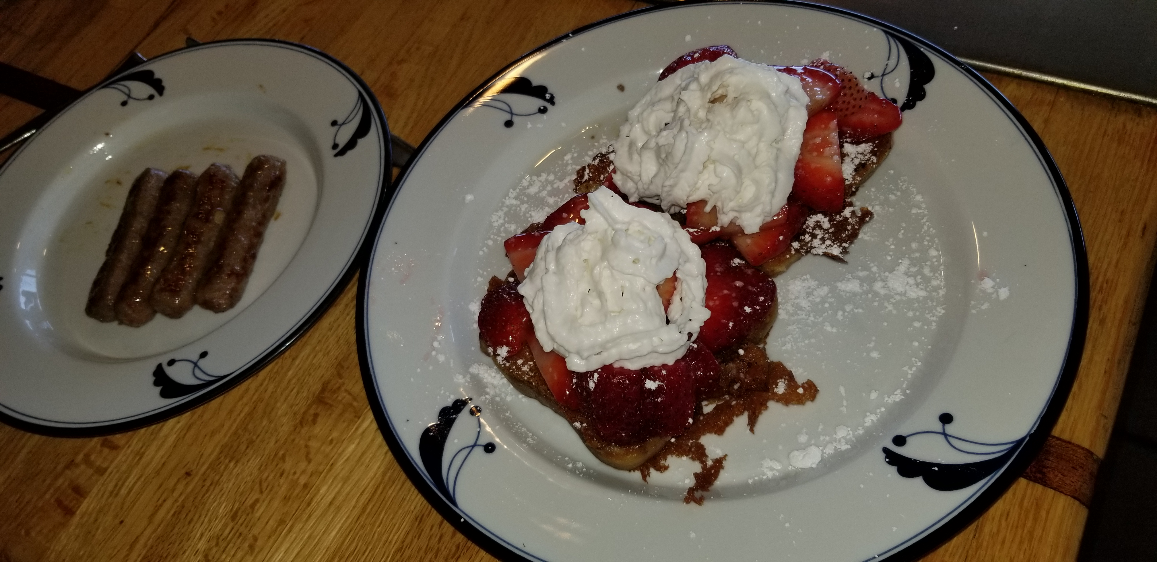
4 pointsStrawberry french toast for the virtual graduating high school senior.
 4 points
 -
4 pointsEighth? What happened to that other one that you bumped off for me about 6 years ago to make me 7th? Am I shrinking, or is it just the kids eating chicken nuggets with growth hormones that accellerated their height. Perhaps they needed a little more to get over the "wall"? Thanks everyone! Had a pretty good day, even if I wasn't feeling that great/was trapped (mostly) indoors. The fam got me a gift that arrived a day late. They couldn't get the one I've been wanting for years, but I think this should do just fine, and help me get started on a better path.4 points
-
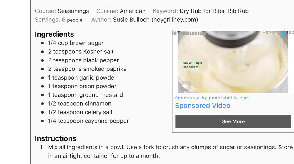
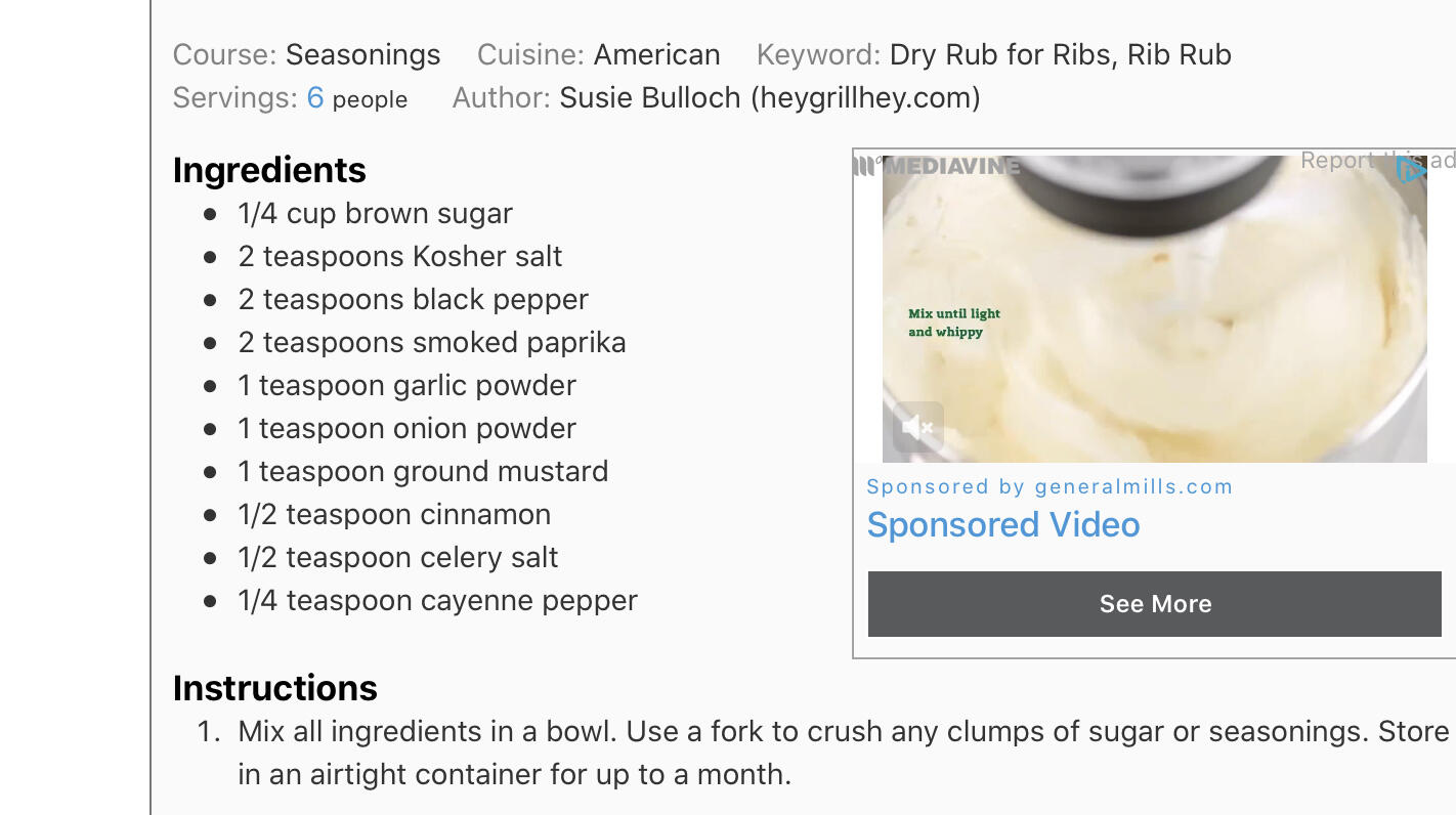
4 pointsMade baby back ribs with the following dry rub: and the following BBQ sauce for the last 20 minutes (2 bastes)
 4 points
 -
4 points
-
Petra Haden is one of the Haden triplets, daughters of bassist Charlie Haden. Super talented family!4 points
-
3 pointsSalmon Tikka Masala on Black (really: purple-black) Rice with cilantro and red chili pepper garnish
 3 points
 -
Trying something different, I uploaded last Friday's set to Mixcloud. First upload I've made there since 2012(!) Tracklisting included.2 points
-
2 points
-
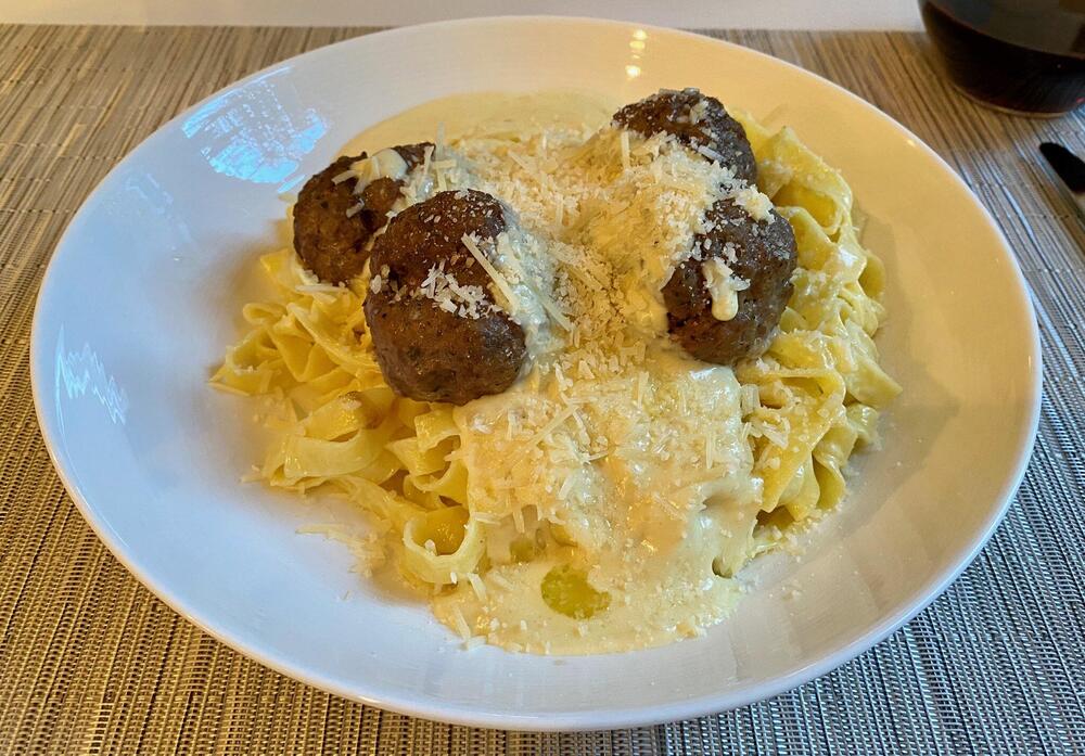
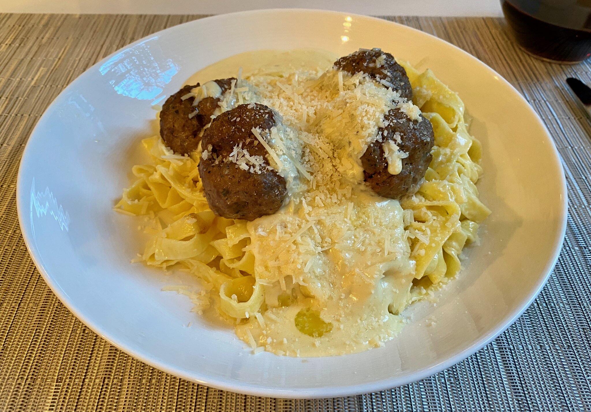
2 points2 points2 points2 pointsSo, what are the odds - found someone in my neighborhood listing a twelve channel Dayton Audio amplifier that they aren’t sure if it works. I picked it up for $50. If it works, that would be wonderful. If not, we’ll, it sure is heavy. I am hoping to have a bit of fun with my audio testing gear tomorrow!2 points2 pointsDamn it Brent! how many times have I warned you about pulling your pork on the forum! And Andrew...My invitation to dinner must have gotten lost in the mail. Sinful pasta was my drag name back in the day.2 points2 pointsPork and veal meatballs with a garlic cream sauce and (sinful) pasta.
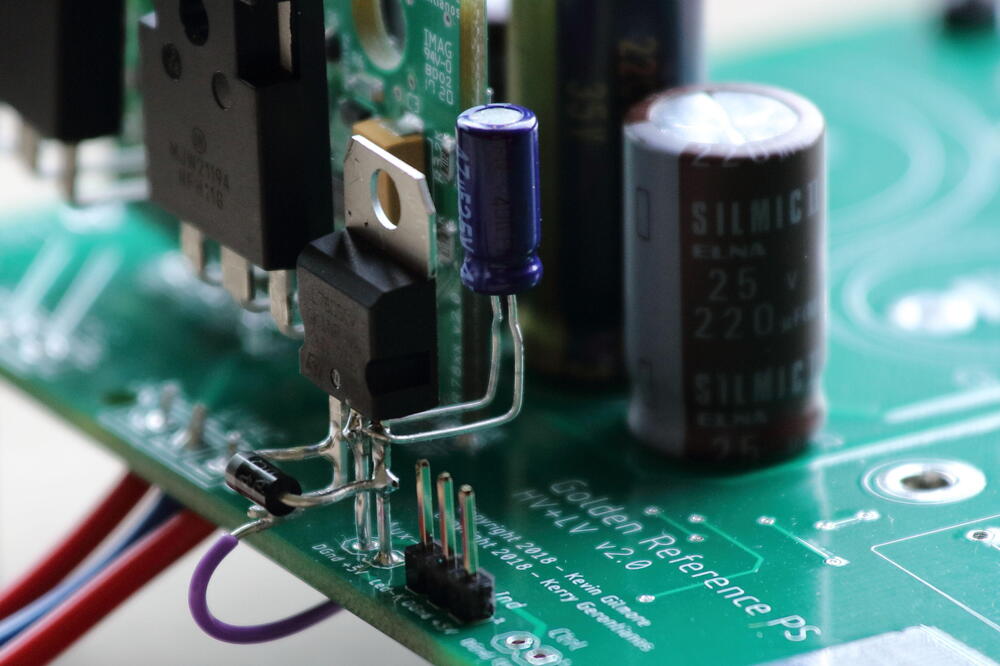
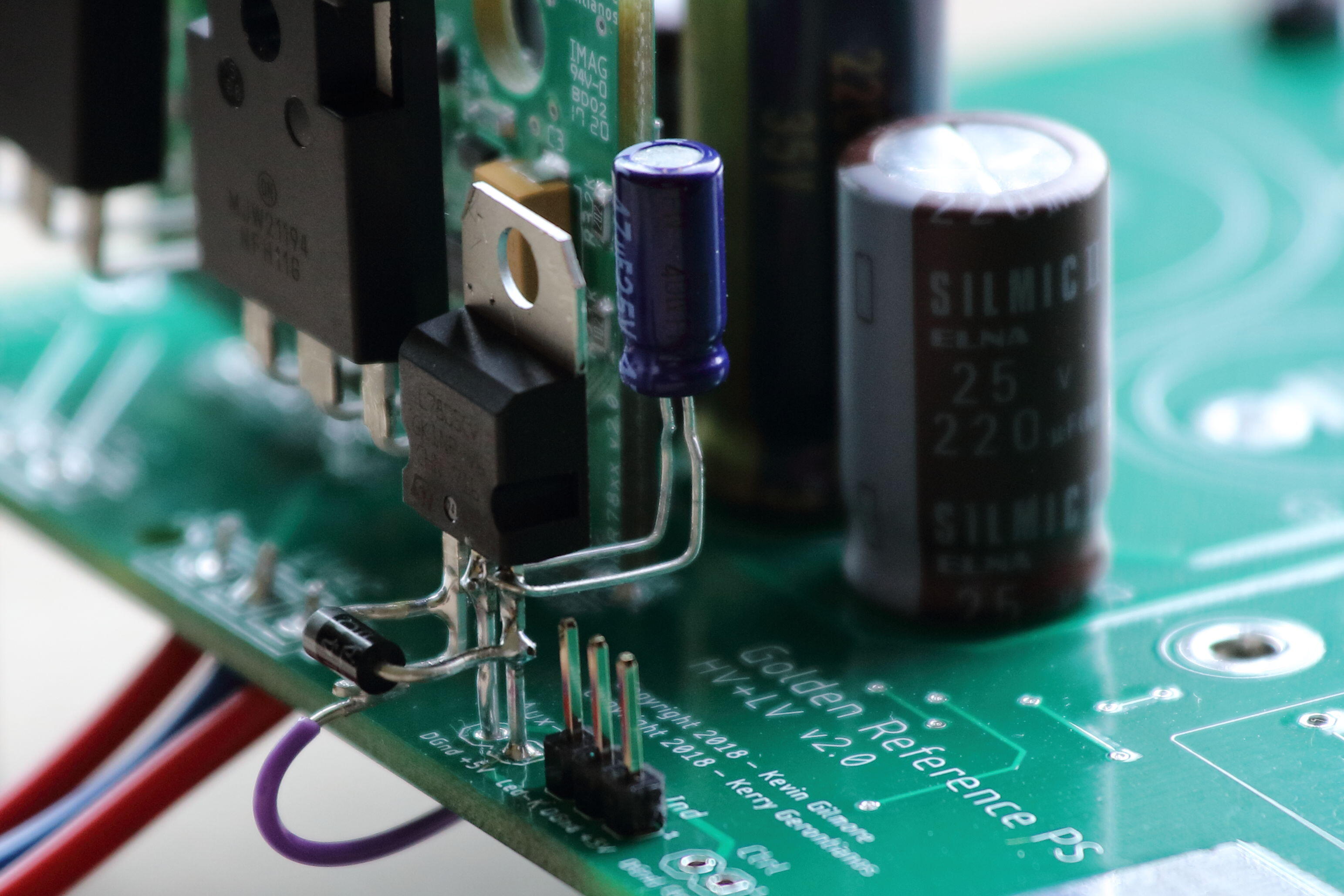
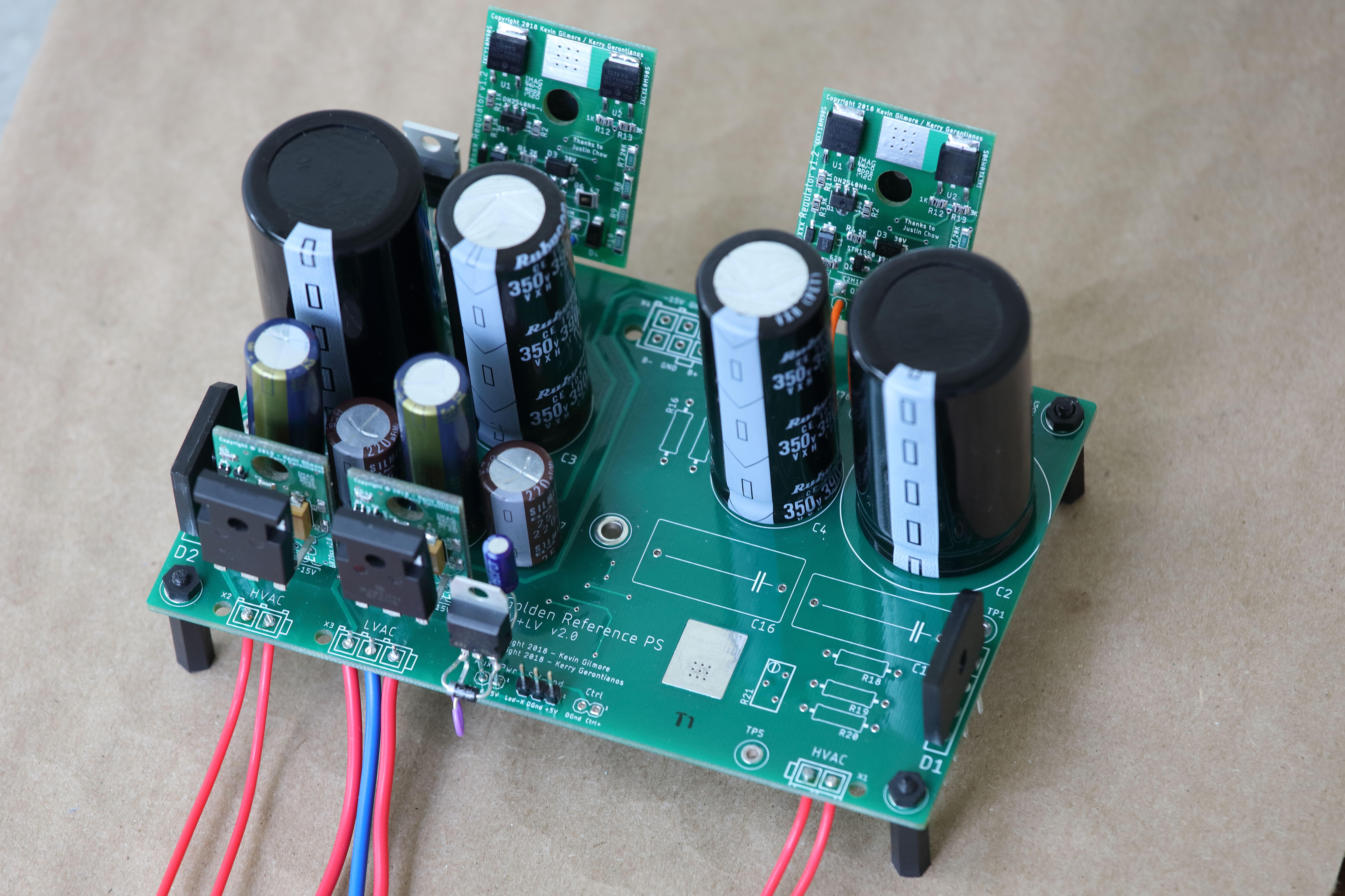
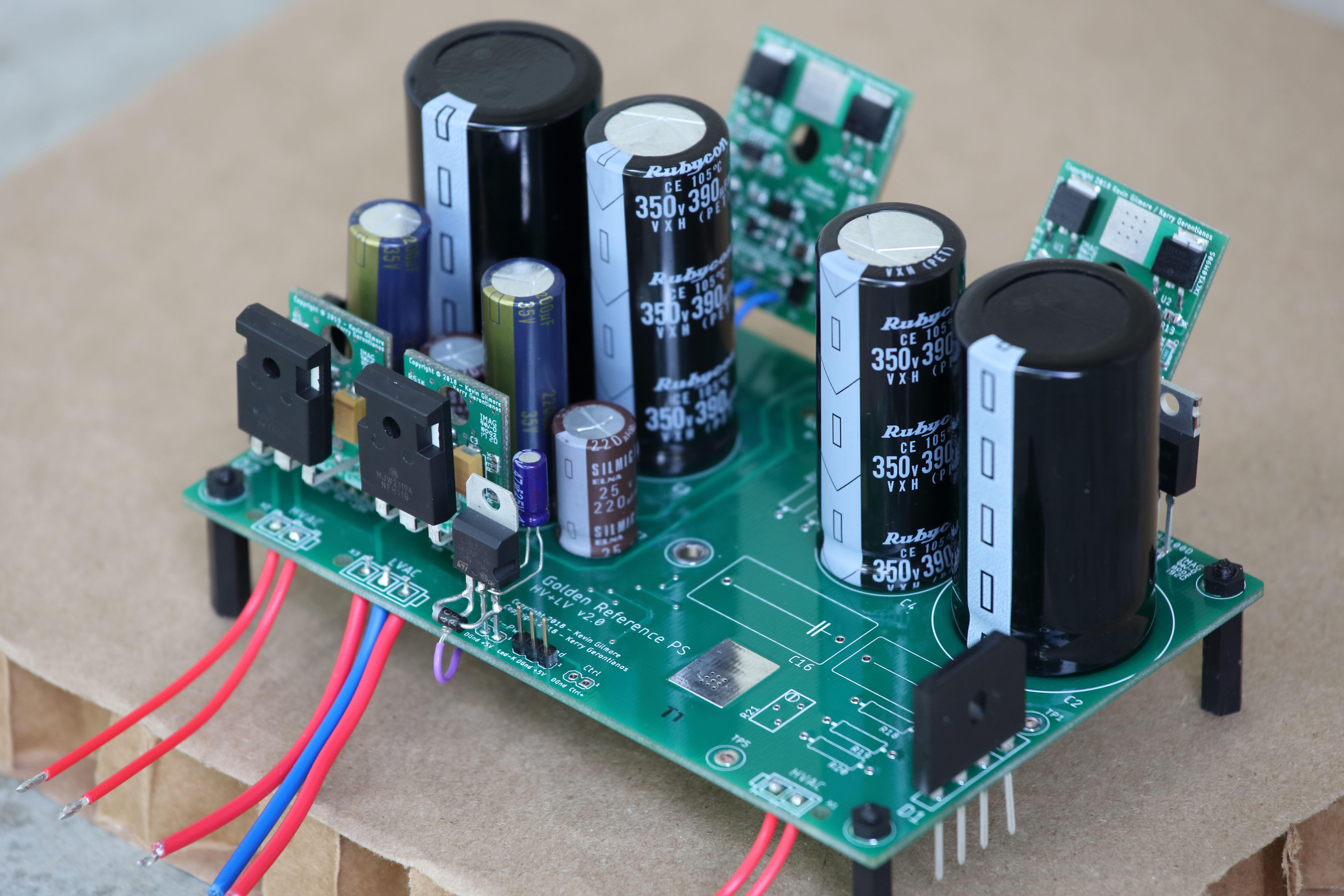
 2 points1 pointThis post is about the auxiliary power supply for the timer circuit. Kerry designed the board to accept an external +5VDC supply for the CD4093BM based timer. After Kerry and I discussed we agreed that there are 3 options: Option 1: For the purist, use an external +5V supply as designed. Note that C17 will see almost the entire voltage drop of the supply so it needs to be rated for 5V or higher. Option 2: Jumper a wire directly from GR78 output to the +5V pin of the Aux - Pwr pads. If you do so, make sure C17 is rated for the GR78 output voltage AND change R1 and R2 from 3K to 10K. For this option, the highest value we could find for C17 in 1210 package is 100uF/16VDC. Combined with 500K for R22, the delay is about 55 seconds give or take a few seconds. I tested this option by rigging in through-hole parts for C17 and R22 and it worked fine. I also added a 12K resistor in series to the LED indicator but this may or may not be needed. Option 3: Solder a 7805 regulator directly in the Aux-Pwr pads and feed theGR78 output to it. I came up with this option mostly because the parts I happened to have on hand and it's what's shown in the pic below. You'll need some capacitance between the Vout and GND pins of the 7805 for it to work (I use a 47uf cap). I also soldered in a 1N4007 zener between Vin and Vout pins to protect the 7805 regulator. I use 330uF/6.3V tant capacitor for C17 and 182K for R22 and the delay is about 75 seconds (I prefer a longer HV delay). You need to jumper a wire from the Vout of the GR78 to the Vin pin of the 7805 (the purple wire in the pic). Options 2 and 3 are easy to do because there is extra hole for the GR78 Vout on the board.
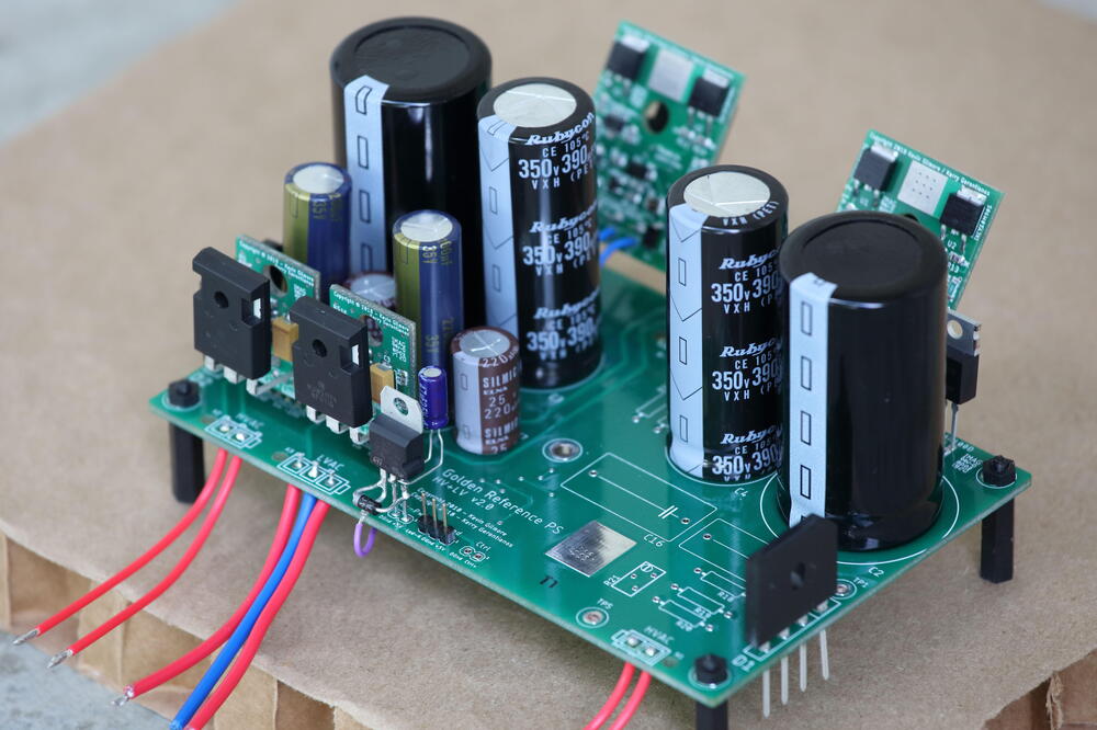
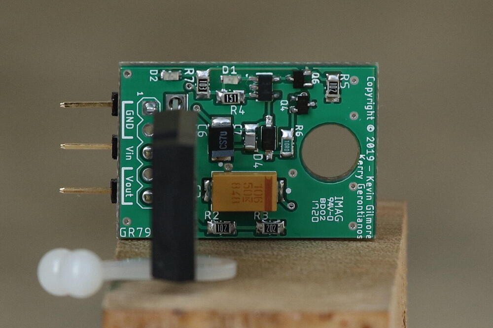
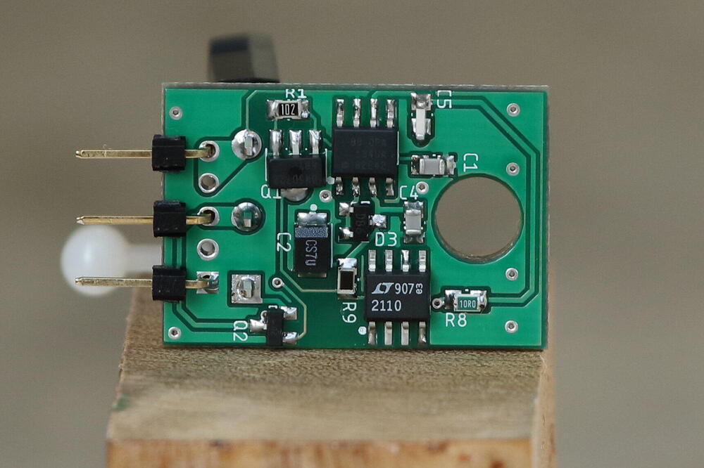
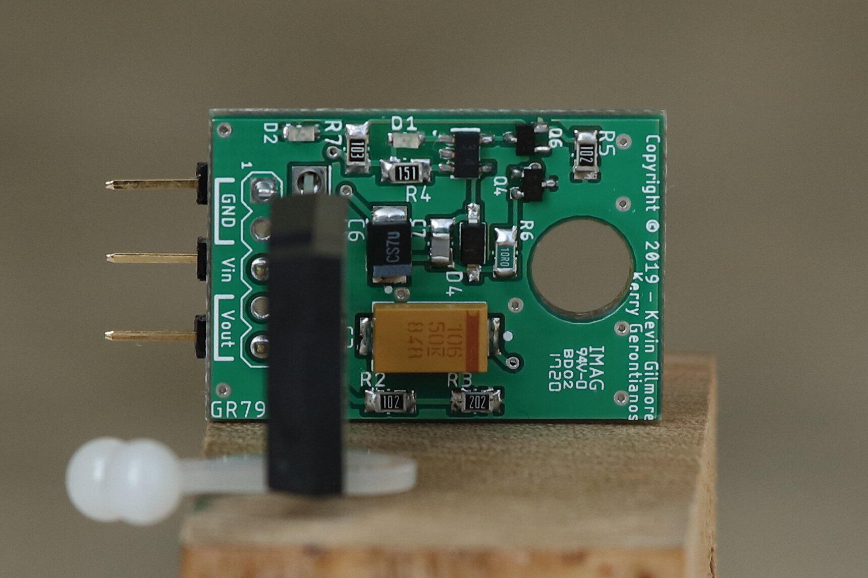
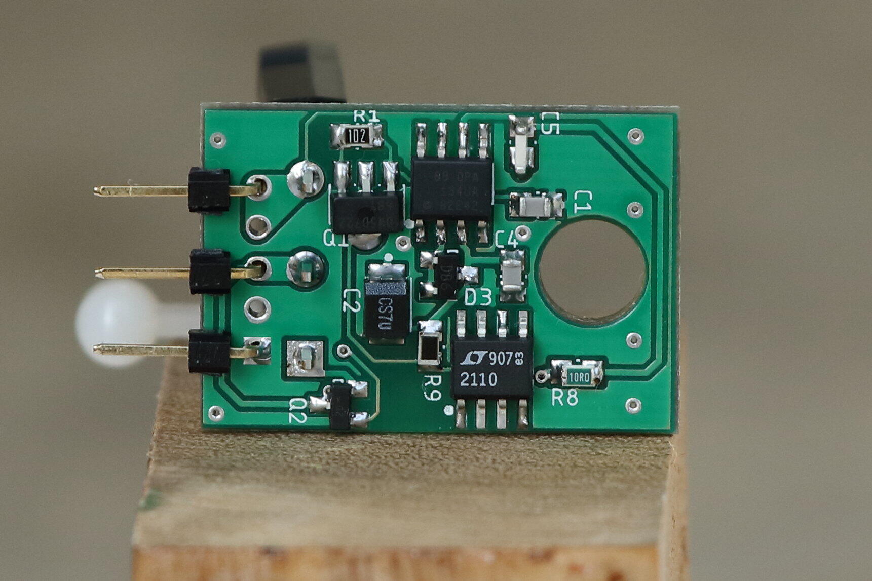
 1 point1 pointOh yes. Betamax, I bought a Betamax back in the day because it was technically superior to VHS, and the tapes were physically smaller. But VHS won the day - so I had a lemon on my shelf. Betamax, VHS - long dead formats both of them now. Like cartridge tapes, cassette tapes, floppy discs, Zip drives and quadraphonic. But who would have thought that vinyl records would make a come back?1 point1 pointHere are a few pics of my test build. GR78/GR79 are set for +/-15VDC, GRHV set for +237VDC/-247VDC. I did not build out the bias supply on this board. I use 182K for R22 and 330uF for C17 which results in timer delay of about 75 seconds. I also tested a 500K/100uF setup which results in about 55 seconds delay. The 100K/470uF combination in the BOM provides about 50 seconds delay. Not these numbers will vary a bit mostly due to the tolerance of the capacitor (see more details in the next post). The PSU main board is of a modular design (see the schematic). It contains the following circuits: 1. A set of GR78/GR79 low voltage regulators. 2. A set of GRHVxx high voltage regulators (B+ and B-). 3. A CD4093BM trigger based timer control (need to provide aux-power, see my posts below). 4. CPC1117N based soft-start for the GRHV. 5. A configurable headphone bias supply (2 outputs are provided - Bias H and Bias L). Note that C1, C2, C3, C4 are pre and post regulation filter capacitors and their values and voltage rating need to be picked based on your needs. The pitch for the pins are all 10mm. C1, C2 diameter need to be 35mm or less and C3, C4 need to be 22mm or less. Pick caps with smaller diameters if you don't like the caps physically touching each other when installed. I mounted the pass transistors of the GRLV in a goofy way and it's not what Kerry has intended. For a normal person, the pass transistors should be behind the PCB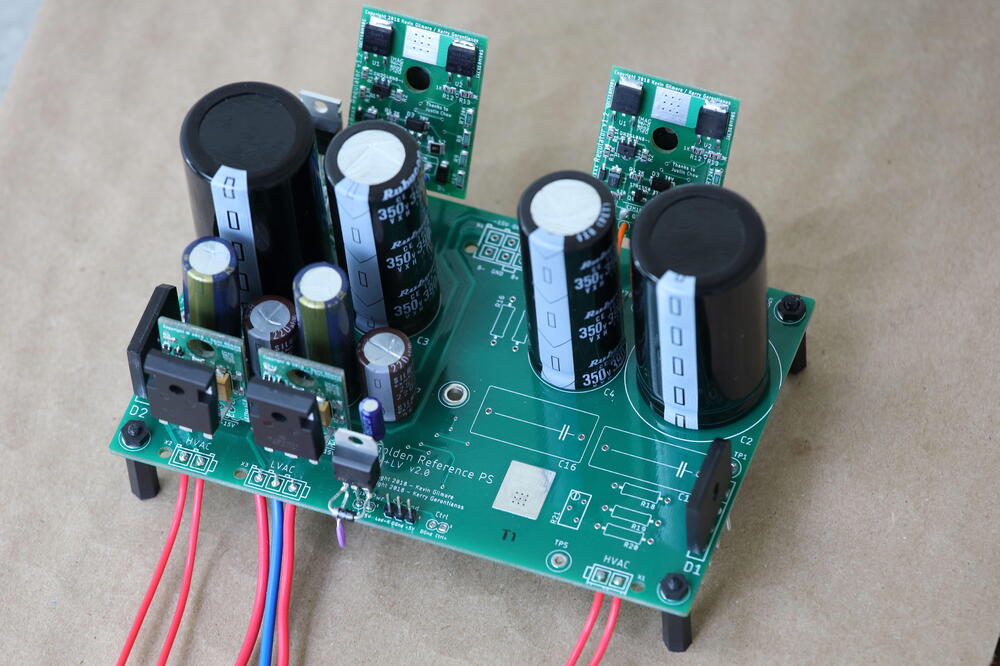
 1 point1 pointHave an exceptional day, but stay away from any and all biscuits! It's already a pandemic for gods sake!1 point1 pointI discovered the problem with chopping chilies in my early 20's. Then going for a wizz. It is a lesson once learnt never forgotten . That picture in the Wikipedia link is a horror story. Look at the front of the stainless steel units that the chef is standing at. And the filthy wiping rag. Sure he has some stuff organised in the foreground, but the rest of the kitchen is salmonella waiting to happen. Ugh. Can you imagine how Gordon Ramsey would take that place apart? It looks like a classic Ramsey's Kitchen Nightmares episode.1 point1 point^Mise en place https://en.wikipedia.org/wiki/Mise_en_place https://www.npr.org/sections/thesalt/2014/08/11/338850091/for-a-more-ordered-life-organize-like-a-chef1 point1 pointOuch. At least it wasn't California Reapers . Small knives are a real danger - I tend to use large ones, kept really sharp. A mate of mine is a pro chef. At least he was - he stopped when they had kids. The hours are stupidly long and he wanted to see the kids grow up. Pre-virus we used to have a cook-in from time to time; beer and cooking for us and wives. And watching him prepare vegetables in particular is a thing to behold. After catering college, he said that the first restaurant he joined would not let him actually cook anything until he had proved his knife skills to their satisfaction - which took 6 months of veg prep and butchery. And when he cooks our kitchen looks like an operating theatre rather the the mess I generate when I cook. He tells me that in a restaurant kitchen you have to have an almost OCD level of tidiness, otherwise you just can't get dishes out on time. I buy our cookware and knives from this place https://www.procook.co.uk/1 point1 point1 point1 point1 point^Someone else did too, apparently https://www.rollingstone.com/politics/politics-features/lola-astanova-trump-779405/ https://www.nytimes.com/2012/01/19/arts/music/lola-astanova-julie-andrews-and-donald-trump-at-carnegie.html1 pointlatest board file with all fixes cfp3rssfixedss - CADCAM.ZIP1 point1 point1 point1 point1 pointHappy Birthday, Brent! Maybe this is the one day a year when you get to have a biscuit and not cause catastrophe? Tell you what, maybe wait till next year. 2020 seems like it's already in enough trouble.1 point1 point1 point1 point1 point1 point1 point1 point1 pointOur little biscuit boy has grown up to be a biscuit man! Happy birthday, buddy!1 point1 point1 point1 pointHappy Birthday, Brent! Maybe for all our sakes you should stick to pandemic appropriate substitutes for the moment.1 point1 point1 point1 pointHappy Birthday, Brent! I wish you a very great day, with your kids, and all the people that these weird days allow around you. Big hugs1 point1 point


































Important Information
By using this site, you agree to our Terms of Use.